| Click On Image For Full Size Image |
Size | Image Description | Contributed By And/Or Copyright |
|
|---|---|---|---|---|
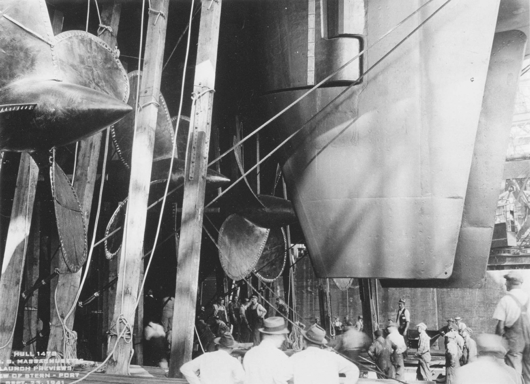
 | 265k | Pre launch preview of the stern section of the Massachusetts (BB-59) 23 September 1941. The ship is provided with two rudders, each of which is actuated by its own steering gear housed in separate compartments. The stearing gears are exactly in duplicate and are independant except that synchronization of the two rudders is dependant upon synchronization of the two selsyn receivers as there is no mechanical or electrical coupling between the two rudder units. The steering stations are in the conning tower,the central station and the secondary conning station, the selector being made by the selector switch in the central station. Shown here is the conning tower instrument mounting rudder stand - Note the assembly of the steering stand. On top the gyro compass repeater mounted between two Steering telegraph transmitters. Receiver selection is made by by the selsyn selector switch in each steering compartment. A total of four selector switches are provided, one in the starboard steering gear compartment, one in the port steering gear compartment, and two corresponding to these in the central station. These switches permit the use of the port or starboard wireway, or both, as the occasion may demand. A combined rudder and steering wheel mechanical indicator is provided on each control unit. The rudder pointer is driven by the follow-up gear and shows the rudder position. The steering wheel pointer is driven by the control gear and shows the equavalent position of the steering wheel. When both pointers are in line, the rudder should be at rest. A dual rudder indicator driven by the follow-up shafts by shafts passing through the separating bulkhead is mounted in each steering gear room. It shows on one dial the position of both rudders and is of special use in emergency steering by the trick wheels. Shown here is the steering emergency signal contact maker ( yellow), a damping cutout push button ( gyro compass). The golden knobs on top are for control of illumination- adjustable shutters. A graduated scale mounted on the inboard ram cylinders, [pictured here are the Missouri's (BB-63)] in each steering compartment indicates the rudder position. Pictured here is the rudder post. An electric rudder angle transmitter driven by the motion from the crosshead, actuates indicators in the steering gear compartments, the three steering stations and the main engine room. Shown here is the After steering station. The electrical indicators are dual, showing the position of both rudders and are combined with the steering order telegraph. Any movement of the control from the Pilot House places a Waterbury pump on stroke and causes the pump to supply pressure fluid to the hydraulic rams, resulting in rudder movement. The rudder movement actuates the follow-up gear and after the steering wheel is brought to rest, the ruddder and follow-up gear continue to move untill the rudder reaches the position determined by the steering wheel. During emergencies the rudders can be operated by several combinations of the two ram cylinders. The steering gear is capable of moving the rudder from 35 degrees Right to 35 degrees left in not more than 36 seconds with the ship going ahead at full speed (28 knots) or from 35 degrees Right to 35 degrees Left in 60 seconds with the ship going astern at 14.5 knots. These rudder velocities are contingent upon the ram pressures not exceeding certain established values. The gear is also capable of stopping and holding the rudder at any angle during the above conditions. | USN photograph courtesy of Pieter Bakels. Sources: General Information Books of South Dakota (BB-57)and Massachusetts (BB-59).
Office of the Supervisor of Shipbuilding For The United States Navy,
Bethlehem Steel Co. Shipbuilding Div., Quincy, Massachusetts. 1942. |
|
 | 208k | Pre launch preview of the stern section of the Massachusetts (BB-59) 23 September 1941. The steering Gear is of the electric-hydraulic type with a double arm crosshead and two pairs of ram cylinders, and two pump units, either one of which can be connected to the rams. The disconnected, or stand-by unit, is normally not running, but under critical conditions of navigation it may be started to permit quick change over if required. The control gear is of the storage motion type, with torque equlizer and rudder follow-up. It operates the servo control cylinder on the main pump from the trick wheel, provided for emergency control, if necessary, in the steering gear compartment or through an electric selsyn transmission from one of three of the remote steering stations. Shown here on the left, a small wheel, a steering emergency contact maker w. below it a damping contact push button w. some cover plates of the selsyn unit- transmitter and the brass wheel. For electric power, either of two main generator switchboards can be utilized as a source. Selection is automatically controlled by the bus transfer equipment by means of voltage relays. The crosshead is keyed to the top of the rudder stock and incorporated opposite arms which are connected by links to two hydraulic rams. The rams are double acting and lie fore and aft, forward of the crosshead.` Hydraulic power is supplied to the rams by either of two similar pump units, each of which is complete in itself and located in the ram compartment opposite that of its rudder. | USN photograph courtesy of Pieter Bakels. Sources: General Information Books of South Dakota (BB-57)and Massachusetts (BB-59).
Office of the Supervisor of Shipbuilding For The United States Navy,
Bethlehem Steel Co. Shipbuilding Div., Quincy, Massachusetts. 1942. |
|
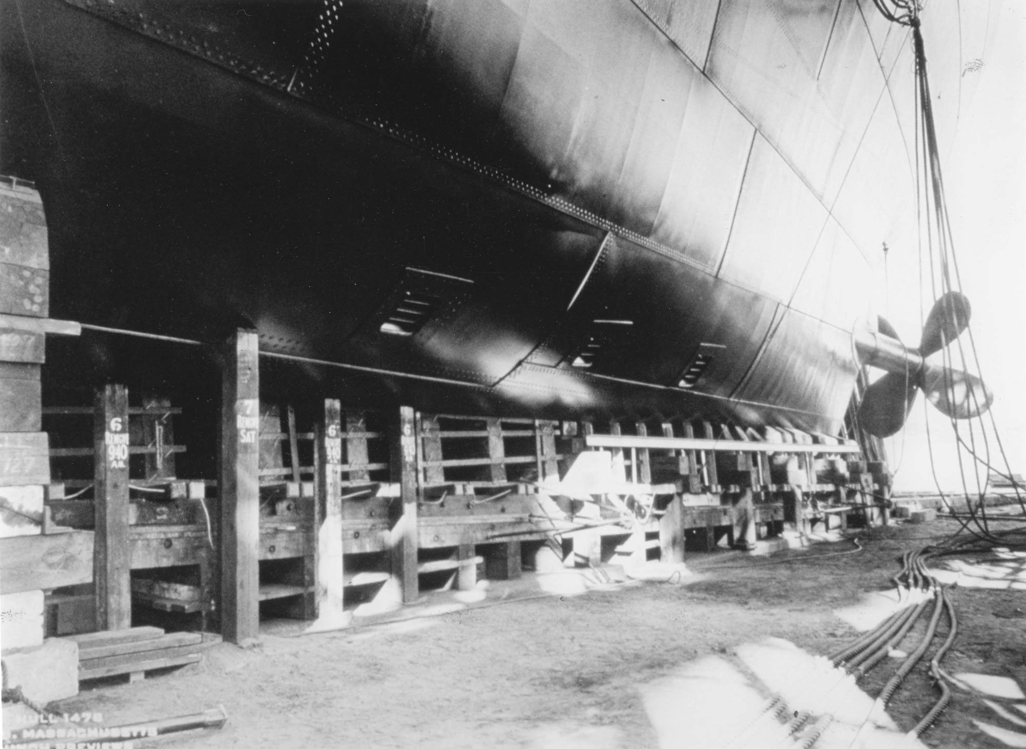 | 224k | Pre launch preview of the stern section of the Massachusetts (BB-59) 23 September 1941. The rudders are of the balanced stream type. The area of one rudder is approximately 273 square feet. There are two rudders, each built up of a rudder main piece of cast steel, class "D" with stiffeners of plates run vertically and longitudinally and with sides of 60# and 30# plates and with a 60# doubler aft of the main piece,all welded together watertight. The rudder stock, a class HG-S steel forging is 26.983"outside diameter at top and 28.005"outside diameter at bottom of tapered section for crosshead. In way of carrier bearing just under the crosshead the outside diameter is 28.750"which diameter comes down parallel 6'-4"to shoulder in stock, at which point the outside diameter reduces to 26.500". From there on down 4'-11-5/8" to a shoulder at top of gudgeon bearing it tapers.62375"per ft. on diameter. At the shoulder at top of gudgeon bearing the outside diameter becomes 211/4" which diameter comes down parallel 4'-10-3/8"to lower end of stock. At the crosshead the stock is bored out at a diameter of 16" for a depth of 9-1/8"from which point on down for a length of 7'-2 1/4" the bore is 20"diameter. The bore is then tapered for a length of 6" from which point on down for a length of 4'-3" the bore is 14"diameter. The bore is then tapered for a length of 6" from which point on down for a length of 5'-8" to bottom of stock, the bore is 10" diameter. By means of a horizontally slotted keyway and a tapered cotter key the rudder stock is forced tight into the tapered portion of the rudder main piece. A sleeve, Comp."G", 22.750" outside diameter is shrunk on the stock in way of the gudgeon bearing, which is at the lower end of the stock. In way of upper bearing in the rudder support a Comp."G"sleeve 30.250"outside diameter is shrunk on the stock. In way of the crosshead two vertical keys are inserted in the stock to transmit the torsional load from the crosshead to the stock. To transmit the torsional load from the stock to the rudder, two vertical keys are inserted in the tapered portion of the stock. The combined weight of the rudder, rudder stock and the crosshead is carried by the crosshead through a stock carrying ring in halves, secured to the crosshead and engaging in a groove in the top of the stock. The crosshead, in turn, is supported on a pedestal carrier bearing with a loose thrust washer which is submerged in an oil bath to insure constant lubrication. The crosshead is the connection for the machinery that operates the rudder. | USN photograph courtesy of Pieter Bakels. Sources: General Information Books of South Dakota (BB-57)and Massachusetts (BB-59).
Office of the Supervisor of Shipbuilding For The United States Navy,
Bethlehem Steel Co. Shipbuilding Div., Quincy, Massachusetts. 1942. |
|
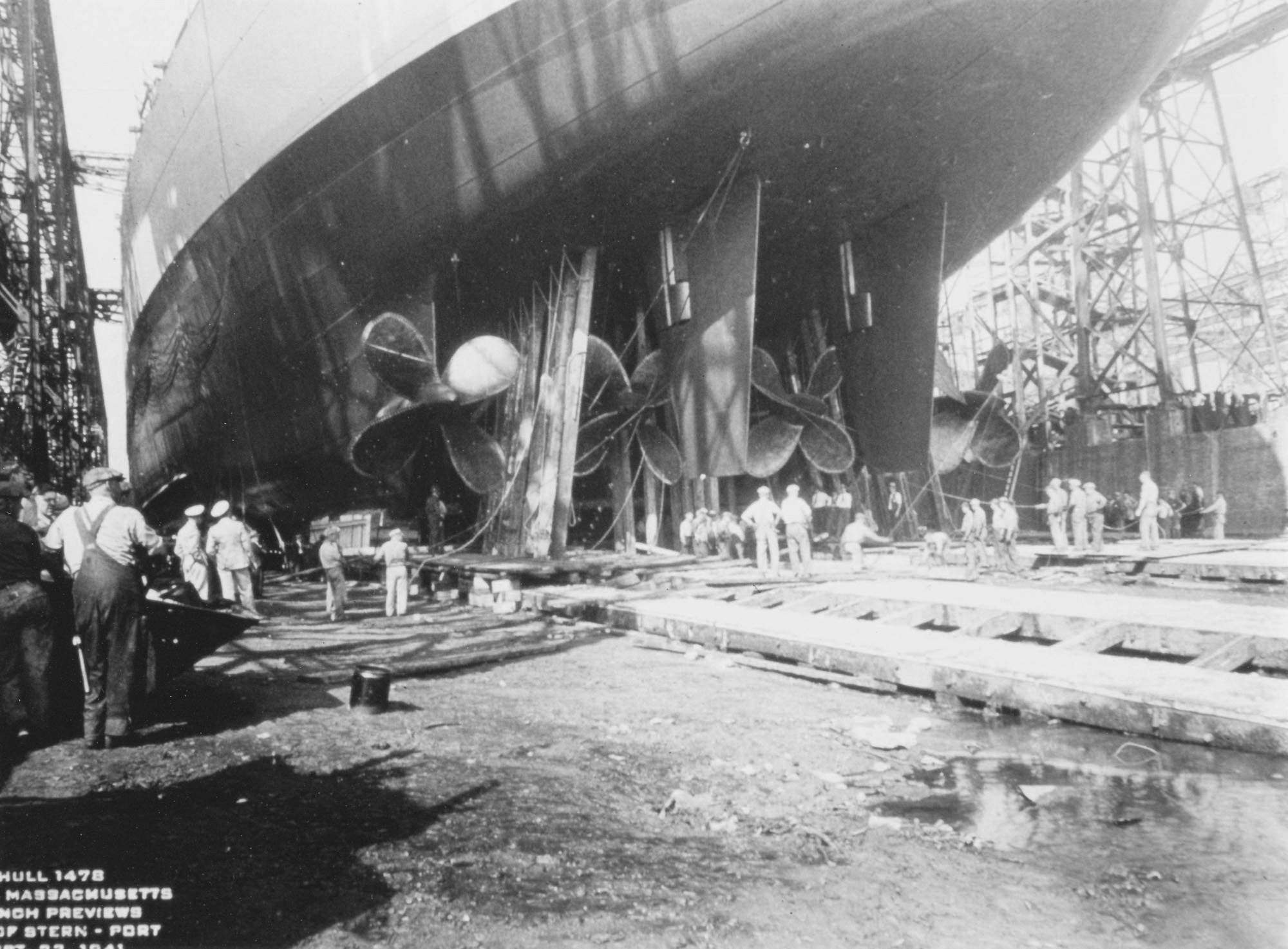
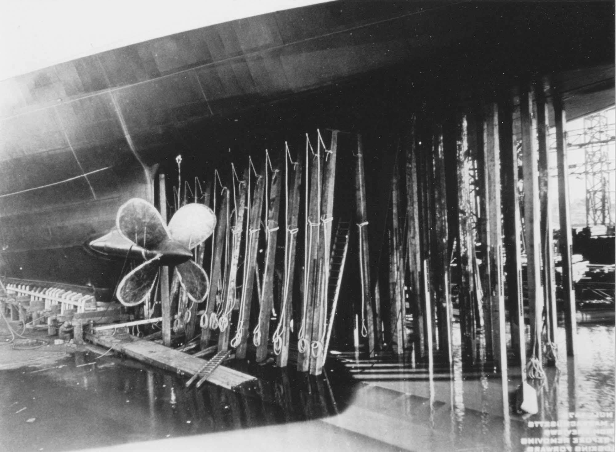
 | 345k | Pre launch preview of the stern section of the Massachusetts (BB-59) 23 September 1941. Massachusetts used 2 Left Hand and two Right Hand, Variable Pitch, Solid Manganese Bronze Propellers. The inboard propellers had 5 blades, diam. 17' 4-1/2 ". The outboard propellers had 3 blades, diam. 17' 8". Shaft diam:22". A phenomenon known as "singing" propeller, a "fluttering" or vibration of the blade serfaces, was frequently observed in ships, excided usually by hydrodynamic forces. The frequency of the sound was usually in the lower audible range and of sufficient amplitude to be truoblesome in the ship as well as fatiquing to the blades. It was also a grave submarine menace! It was corrected by reduction of the exciting forces and increasing the damping by sharpening the propeller blade edges for distances up to 3 inches from the edge. The edges had to be no thicker than 1/32 inch on the trailing edge or tip and the outer portion of the leading edge to insure freedom from "singing". Additional care had to be exercised in handling such propellers and soft wood blocks were used for the protection of the blade edges when turning the propeller over in the shop or in a yard. The edges were protected by canvas and metal edge strips when shipped or carried on board ship, except when crated. | USN photograph courtesy of Pieter Bakels. Sources: General Information Books of South Dakota (BB-57) and Massachusetts (BB-59).
Office of the Supervisor of Shipbuilding For The United States Navy,
Bethlehem Steel Co. Shipbuilding Div., Quincy, Massachusetts. 1942. |
|
 |
2.1m | "Constitution raking H.M.S. Java, 29 December 1812 off the coast of Brazil." PDF of Arrangement of Shafting - Plan & Sections - South Dakota (BB-57) and Massachusetts (BB-59) dated 22 June 1939. |
USN photo submitted by Pieter Bakels. | |
 |
813k | View of the ship's stern, showing her twin outboard skegs, with five-bladed propellers at their after ends. Four-bladed inboard propellers are faintly visible, with the ship's twin rudders directly aft of them. Taken in drydock at the Newport News Ship Building and Drydock Company, Newport News, Virginia, 13 March 1942. | Text courtesy of photo Naval History and Heritage Command # NH 93910, from the collections of the Naval Historical Center. Photo courtey of Pieter Bakels. | |
 |
787k | Photo show the "skeg" hull form that all the fast battleships had. The Indiana (BB-58) and her sisters were unique in the fact that their skegs were on the outside of the hull and contained their outer propeller shafts. | Text courtesy of photo Naval History and Heritage Command # NH 93909, from the collections of the Naval Historical Center. Photo courtey of Pieter Bakels. | |
 |
959k | Port side view of the outer propeller shafts of the Indiana (BB-58) in drydock at the Newport News Ship Building and Drydock Company, Newport News, Virginia, 13 March 1942. | Photo courtey of Pieter Bakels. | |
![ram cylinders, [pictured here are the Missouri's (BB-63)]](http://navsource.org/archives/01/015910a.jpg)
| Back To US Battleship Construction Index | Back To The Main Photo Index | Back To The Battleship Photo Index Page |
This page is created by Pieter Bakels and Michael Mohl & maintained by Michael Mohl
All Pages © 1996 - 2025, by Paul R. Yarnall NavSource Naval History. All Rights Reserved.