| Click On Image For Full Size Image |
Size | Image Description | Contributed By And/Or Copyright |
|
|---|---|---|---|---|
 |
90k |
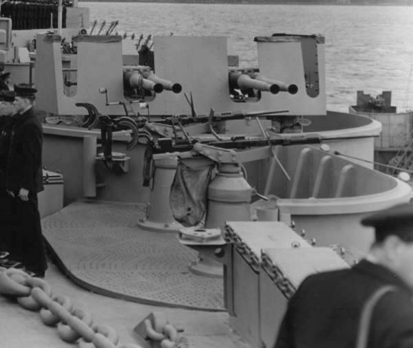
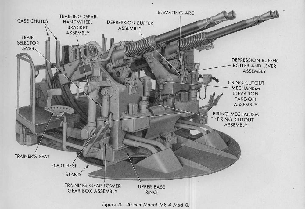
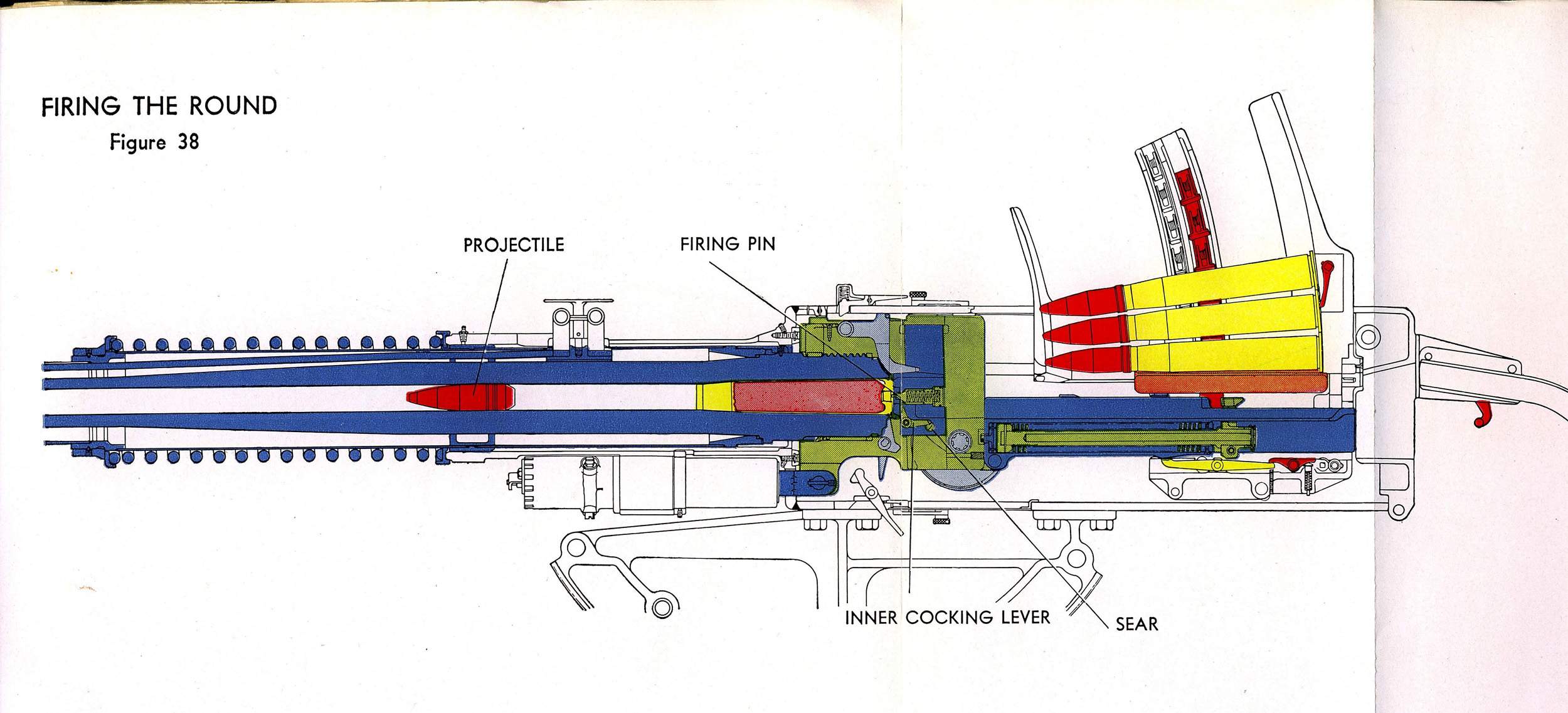
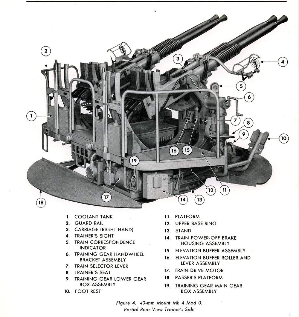
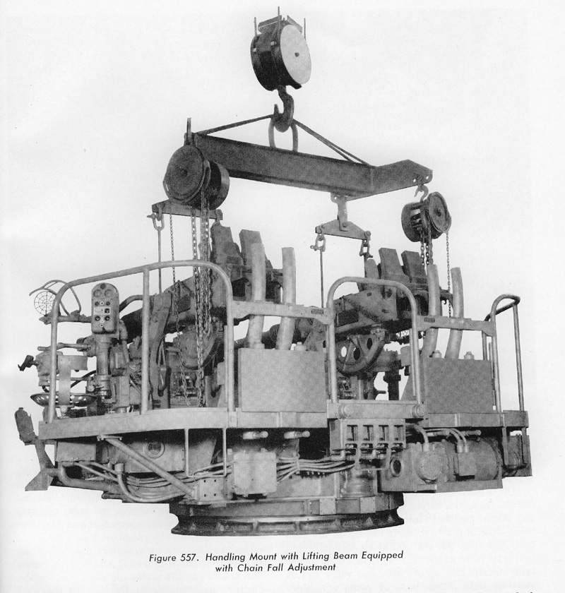
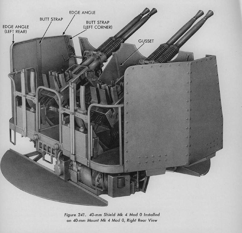
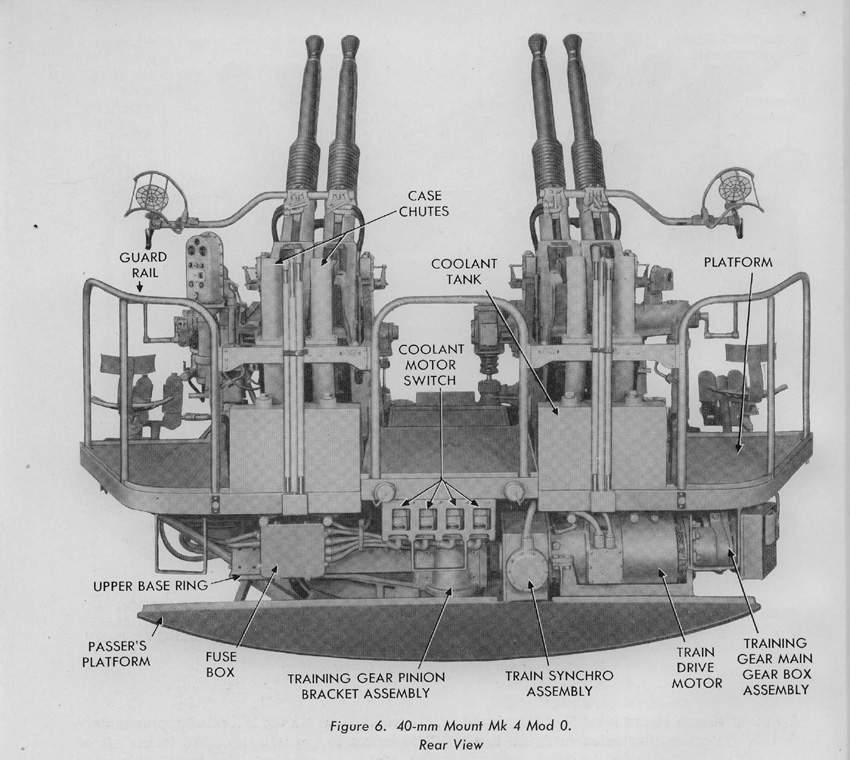
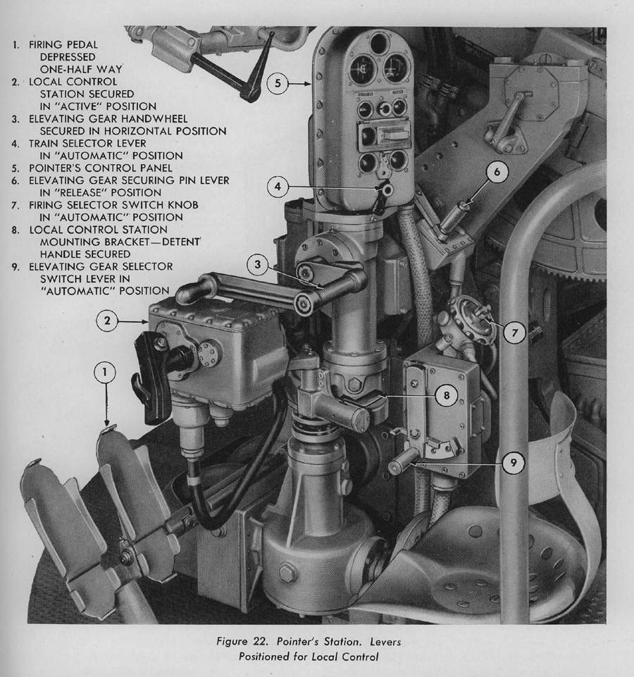
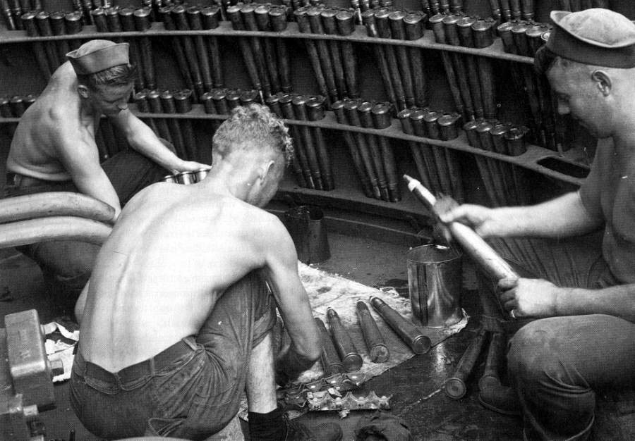
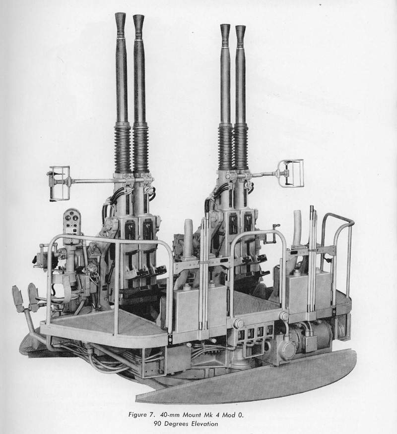
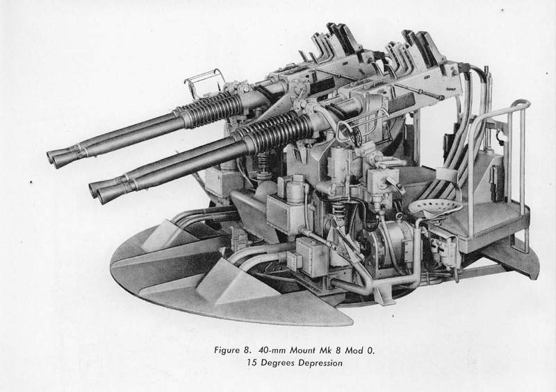
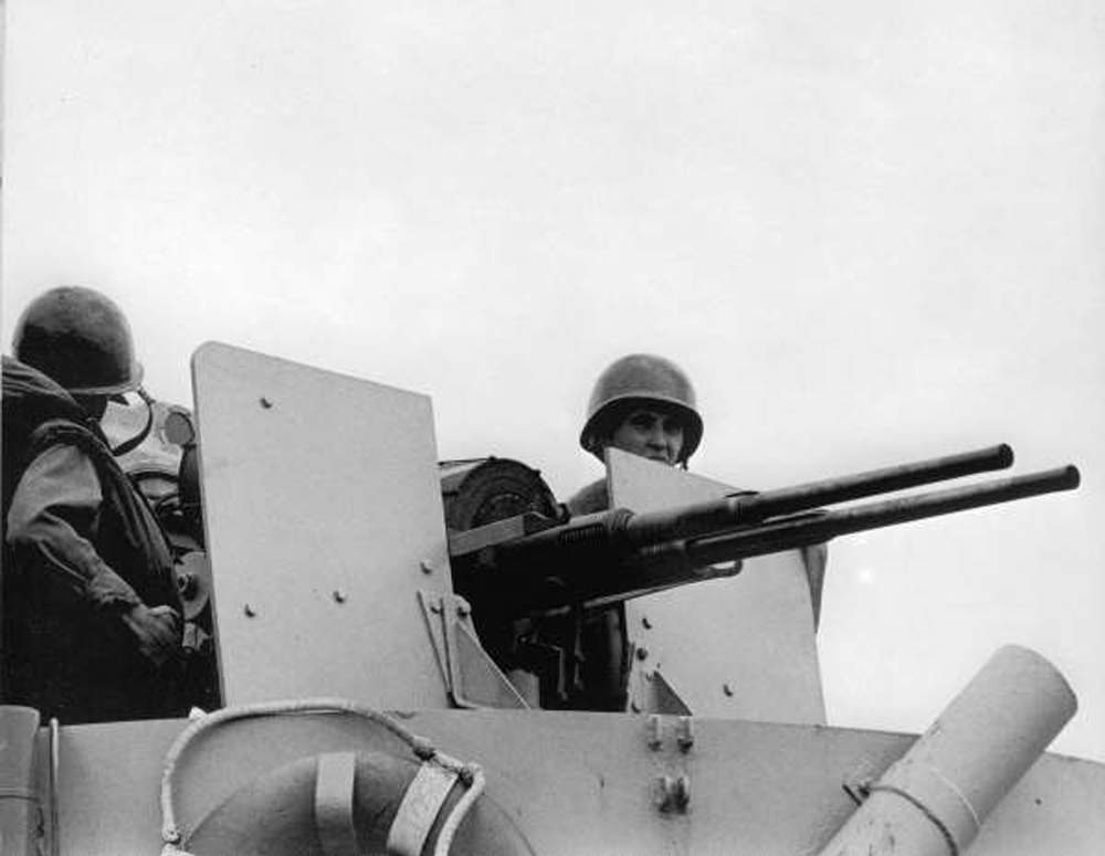
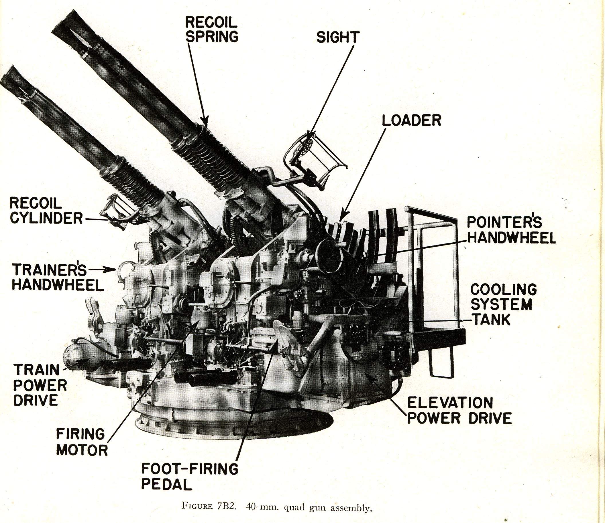
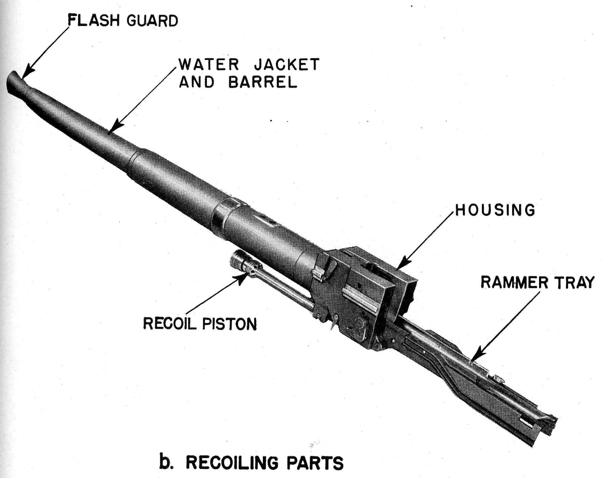
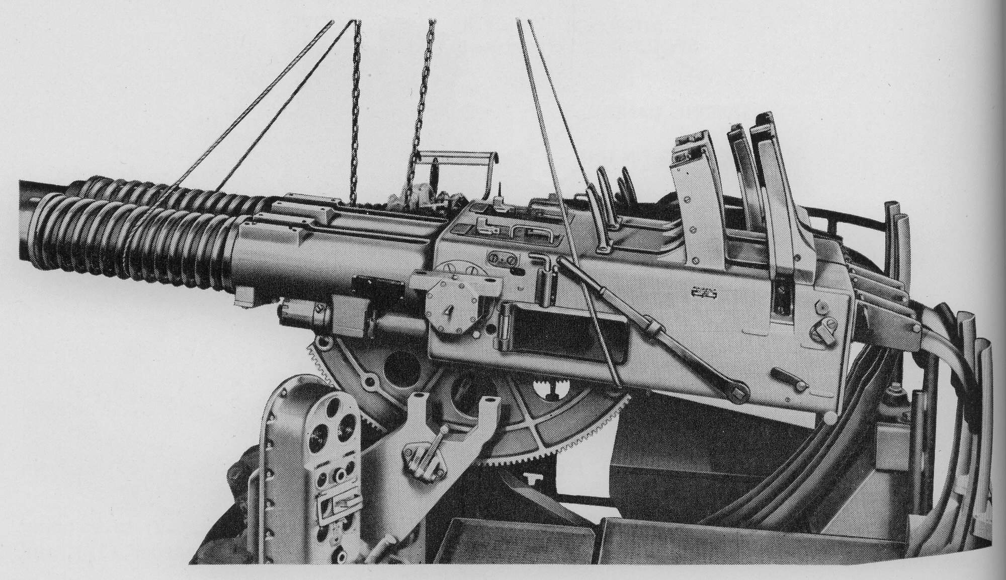
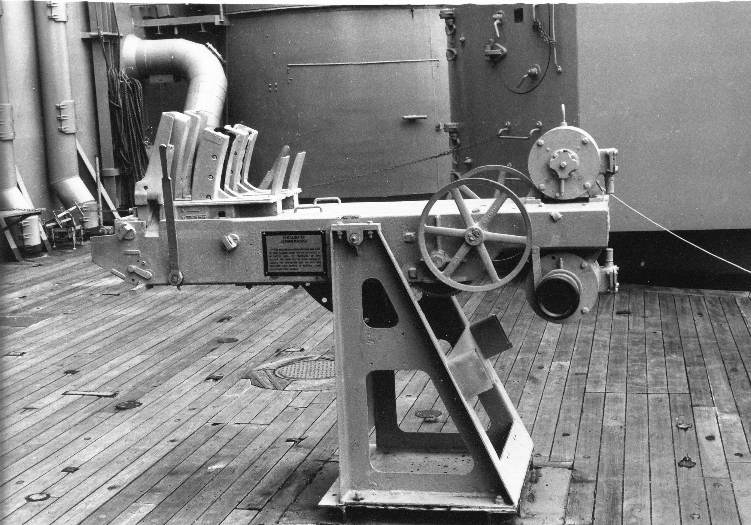
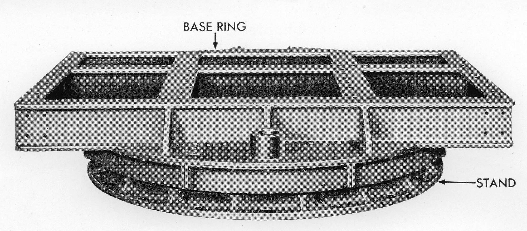
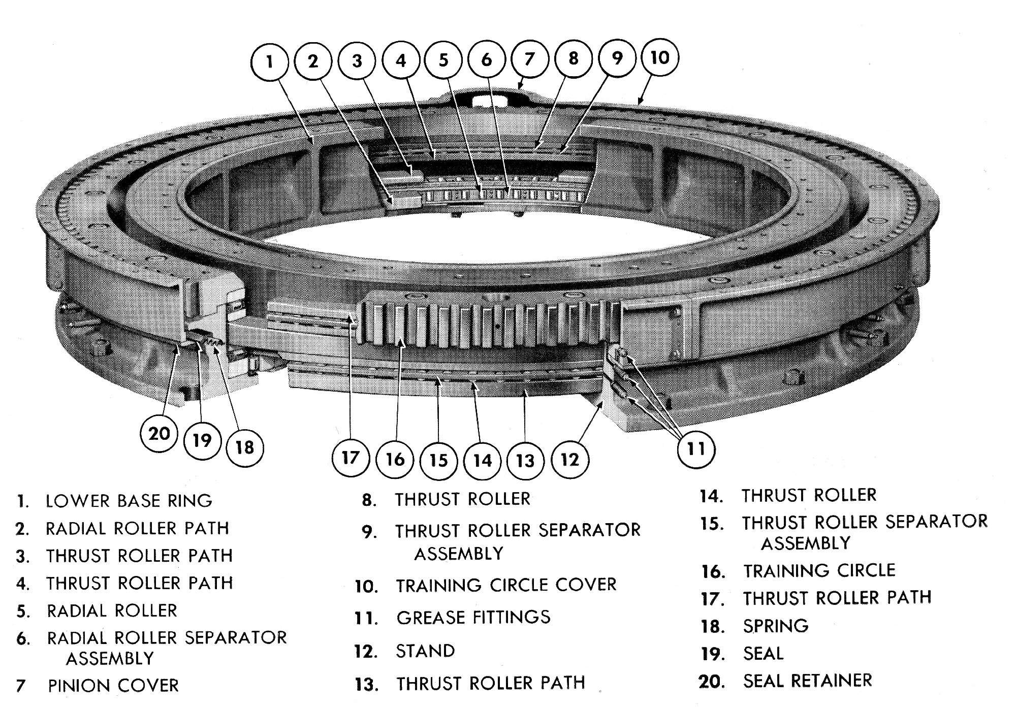
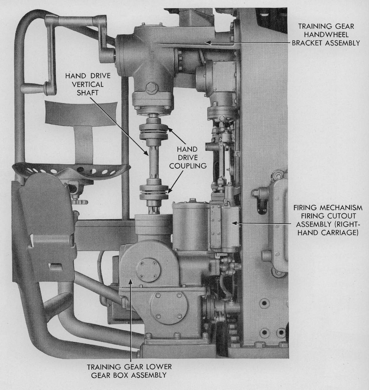
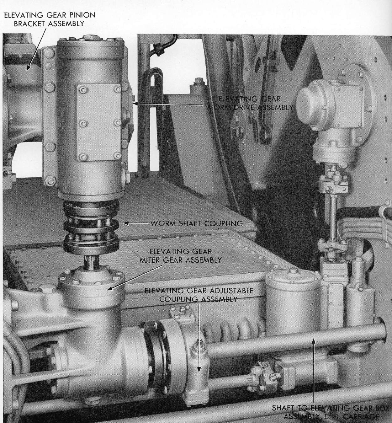
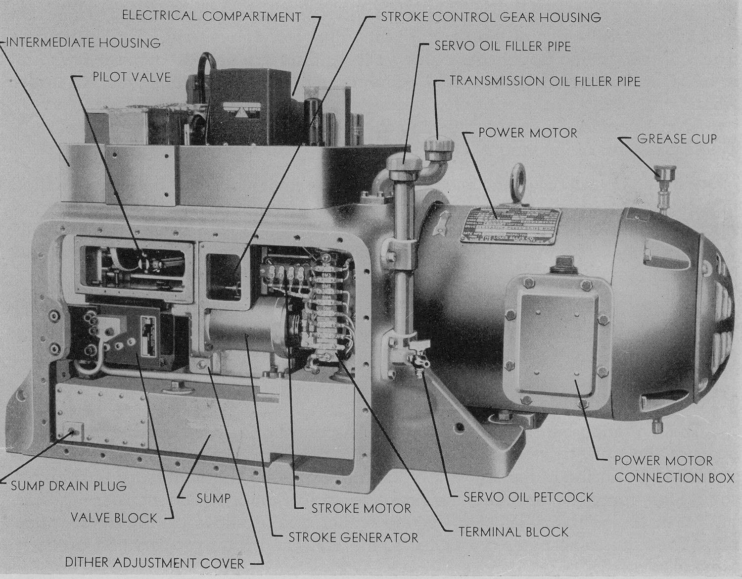
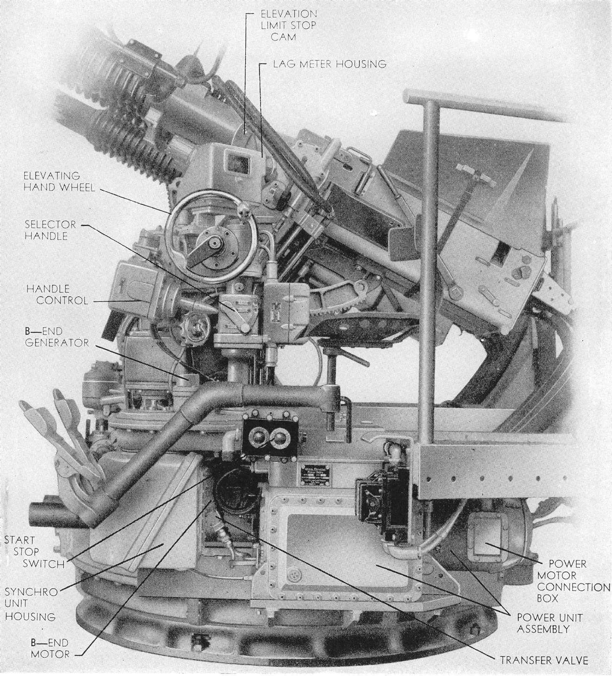
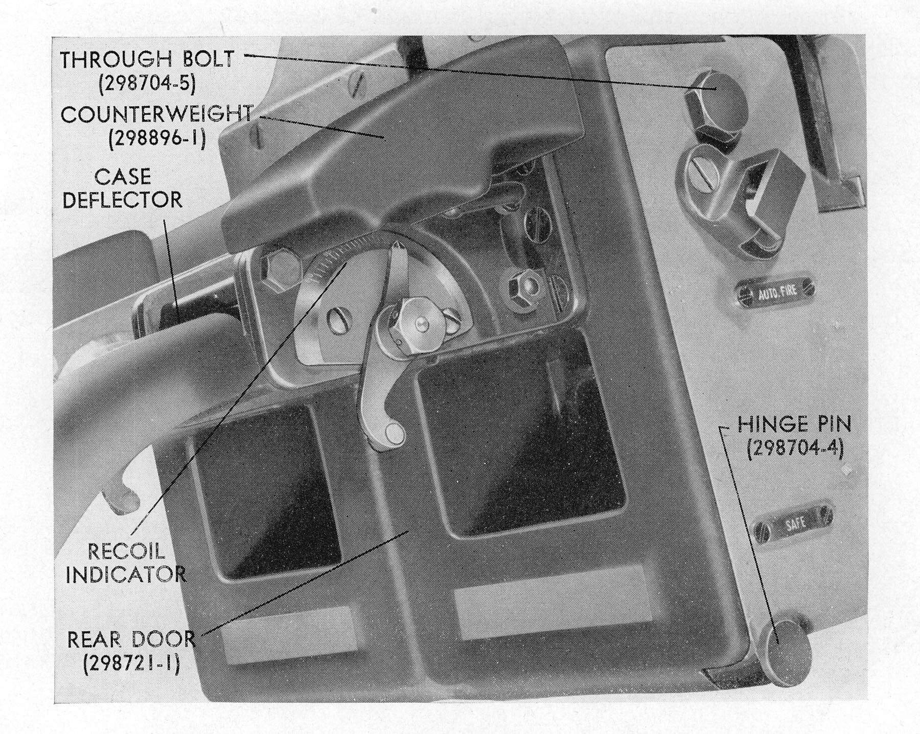
40MM Bofors - Prelimanary: Much of the Bofors enormous popularity could be traced to the much greater power of its ammunition compared to that of the 1.1in. Muzzle velocity rose to 2890ft/sec and the standard tracer round burned for 8.5-10.5 seconds (4200-4500yds). It fired armor-piercing, high explosive and incendiary rounds with a projectile weight just under 2lb, more than twice that of the 1.1in. No VT fuze was available for this weapon during the war. The rate of fire per barrel slightly exeeded that of the 1.1in. The Bofors as said before, was liked for its high power, its ruggedness and its simplicity of operation and maintenance. The percentage of aircraft kills attributed to it grew as the Japanese came to rely more heavily on suicide attacks late in WWII. Between 1 October 1944 and 1 February 1945 about half of all aircraft shot down by US surface ships were credited to the Bofors . In the extensive kamikaze rearmament program of 1945 in which many Fleet destroyers were fitted with additional Bofors guns at the expense of their torpedo tubes, the same sort of popularity shows. Only at the very end of WWII it became clear that a replacement was needed as the Bofors was not able to destroy an approaching kamikaze soon enough to keep it from hitting. Firing a much heavier shell, the 3in/50 could put up more metal than could the Twin 40mm and more effectively, since it would fire VT-fuzed shells. Ammunition for the Bofors was loaded in the form of four-round clips atop the breech mechanism, each full fixed round weighing about 4.8lb, for a total of about 19. The Bofors feed atop the gun could hold two clips, so that fire could be maintained continuously passing clip after clip into the gun. The first series of quadruple 40mm mounts were allocated to the South Dakota class (BB-57 - 60) battleships, which received six MK.2. The Mark 4 The Mk.4 was a lightweight quadruple mount developed by Northern Ordnance, in which about 1000lb was saved by the use of a GE drive, and an additional 2500lb of electrical equipment, including amplidyne motors, was stowed below decks. About 100 had been made by VJ-Day. It weighed 25,140lb, elevated/trained at 55 degrees per second and its introduction shows the needs of the Fleet of 1945. It had elevation limits of +90-/-15 degrees. Although meant to be replaced in 1945, by the 3in/50, it remained through the 1970's for lack of funding. Eventually a VT-fuze was developed for it but there seemed to be no interst in new 40mm development. Machine Gun Battery Designed to give the South Dakota (BB-57) the maximum defensive fire power against enemy aircraft, the machine gun battery was divided into four sectors. Sector 1 had a defensive area starting from the bow in a clockwise direction to 090 degrees relative or the starboard beam. In this sector there were eighteen 20mm guns and four 40mm quads. The quads were numbered from one to four while the 20mm’s were formed in groups numbering from one to seven, starting from the bow and going aft. The control station for sector I was located on the starboard side of the platform outside the Batt II level and was in communication with all quads, 20mm groups, clipping rooms and Mark 51 directors in the sector over the 1JY telephone circuit. Each individual group or quad had a 1JY outlet. The sector officer was in general over-all charge and controlled the fire of his sector, directing what 20mm groups and what 40mm quads should fire at various incoming targets. Carrying out the sector officers orders were the 20mm group captains and 40mm quad captains who were in charge of each individual station. It was their duty and responsibility to see that the control officer’s orders were carried out, that all casualties were repaired immediately and to take over the direction of defensive fire should they lose communication with the control officer. Sector II included all machine guns forward of frame 85 on the port side. It had a defensive area covering from 270 degrees relative (port beam) forward to the bow, 360 degrees. This sector had three 40mm quads and eighteen 20mm guns in it, both numbered as in Sector I, starting from the bow and going aft. The control station was located on the port side of the platform outside the Batt II level and was connected to all quads, 20mm groups, clipping rooms and Mark 51 directors by the 2JY telephone circuit. All orders from the sector control officer went over this circuit. As on the machine gun stations, the group captains and quad captains were in charge of their individual stations. Generally, these men were petty officers and experienced in the handling of each station. On the top of Turret Two were five 20mm guns, two of which belonged to Sector II and the three starboard guns came under the control of Sector I. These guns were essentially for defense against dive bombers since only one gun in each sector could be fired safely at targets passing up or down either beam. Each machine gun station had a certain amount of “ready” ammunition standing by for use at all times, however the main source of ammunition supply for the forward sectors was in the large 20mm clipping room forward of the wardroom, a 40mm magazine located on the first superstructure deck just aft of Turret Two and a 40mm magazine located in the forward part of the superstructure on the 5th level (housetop level). The last mentioned magazine was connected to magazines below the main deck (3rd deck) by means of an ammunition hoist. All these stations were manned during “General Quarters”. Sector III had a defensive area starting from 090 degrees relative extending to 180 degrees (starboard beam to directly astern). It had five quads and twenty-one 20mm guns, the latter being formed into seven groups varying from one-gun groups to five-gun groups. The control officer for this sector was located on the starboard side of Sky Aft which was on the after side of the Main Battery Director Two. He was in communication with all stations in his sector over the 3JY telephone circuit. Aside from the “ready service” ammunition, the main supply of ammunition came from 40mm magazines adjacent to the quads and from the 20mm clipping room known as Clip Aft. Sector IV covered an area extending from dead astern (180 degrees) to 270 degrees (port beam). As in Sector III this sector had five 40mm quads and twenty-one 20mm guns. These were numbered from one to five in the quads and from one to seven in the 20mm groups. The sector control officer was located on the port side of Sky Aft and was in contact with all quads, 20mm groups, clipping rooms and Mark 51 directors over the 4JY telephone circuit. The sector control officer issued all his orders and controlled his sector over this local circuit. As in all other sectors, the group and quad captains controlled their individual stations with respect to fire distribution should communication with the sector officer fail. All stations in Sector IV had similar sources of supply as in Sector III. In general over-all charge of all four sectors was the Machine Gun Officer whose station was in Air Defense during “General Quarters”. He wore the 5JY telephone and was in contact with each sector over the same circuit by means of a 5JY phone talker standing alongside each sector officer. He could, by means of the selector switch, cut in on any of the four sectors and thereby talk to any station he desired in that sector. The Machine Gun Officer directed and distributed the fire of his sectors depending upon the various types of attack. He received a continuous stream of radar reports and other pertinent information from his talker who wore the 5JP telephone, the main A.A. defense telephone circuit and relayed this information on to the sectors concerned. On South Dakota the senior Marine officer was also the Machine Gun Officer. He was in over-all charge of all maintenance and training as far as the machine guns were concerned. 40mm Section 40mm A.A. (Bofors) Machine Gun and Characteristics The 40mm twin machine gun (which formed one half of a quad mount) was basically the same as the usual naval gun. It consisted of four main parts: 1. The gun barrel, 2. The breech mechanism (breech casing), 3. The automatic loader & 4. The recoil system. The barrel was an all-steel forging secured to a breech ring by means of a bayonet type threaded area and was attached or unattached by one half turn of the barrel. The barrel was covered by a water jacket, sealed at the breech end by a copper gasket and packed at the muzzle end by two rings of woven packing. The muzzle end was fitted with a flash guard. The barrel and breech ring were supported in the gun mechanism by a bearing on the outside diameter of the water jacket toward the muzzle end and by guide lugs on the sides of the breech ring, which, in turn, slid on surfaces provided in the breech casing (body). The breech ring was fitted inside with a breech block (similar to 5”/38 breech plugs) that was actuated by a helical spring. The helical spring drove a splined shaft to which two cranks were fitted. The outer extremities of these cranks were fitted with heart shaped projections that fitted into sliding surfaces on the slides of the breech block. The breech plug itself was fitted internally with the firing pin and its operating mechanism. To the forward surfaces of the breech ring, below the part to which the barrel attached, were two lugs to which were attached the buffer piston, the function of which was to control both recoil and counter-recoil. The buffer, which was mounted to the underside of the breech casing, was fitted internally with a piston which fitted the inner diameter of the buffer cylinder; but the piston itself was provided with a hole through the center in which was inserted a throat bushing and through this bushing extended a variable diameter rod which controlled the area of the orifice, thereby making it possible to control the amount of recoil or counter-recoil at any point in the travel. The buffer was fitted with an adjustment to control the speed of counter-recoil. On the rear surface of the breech ring, two lugs were provided to which a total of eight shells could be placed in groups of four each. The loader mechanism provided with guides, holding tray was supported on suitable surfaces in the loader mechanism which permitted the tray to travel with the breech ring and barrel in recoil and counter-recoil. Around and above this tray was the loading mechanism in which a total of eight shells may be placed in groups of four each. The loader mechanism was provided with guides, holding pawls and feeding pawls which prevented the live ammunition from falling out of the loader even when the gun was elevated 90 degrees. The loading pawls operated to feed in one shell each time that the gun recoiled. The feeding operation was accomplished by means of revolving feed wheels which made one quarter turn during each recoil and in doing so, removed the clip, discharging it out the side of the gun mechanism. When the shell was fed onto the tray, it was grabbed by two rammer forks, which were released in automatic fire by means of a pawl operated by a projection on the lower surfaces of the loading tray. In single fire, the rammer forks were released by a foot treadle actuated through connecting levers. When the rammer forks were released as mentioned above, the shell was thrown forward over the loading tray through an opening in the breech ring into the barrel. In passing into the barrel, the shell contacted the extractor levers, moving them with the shell and disengaging them from the breech block which, up to this time, had been held open by these two extractor levers. A tapered surface on the forward edge of the breech block came in contact with the shell, forcing it home in the barrel. As soon as the breech block reached the upper-most portion (closed position), the firing lever was automatically tripped, causing the gun to fire and recoil. In recoil, a crank attached to the splined shaft, previously mentioned, was brought into contact with a cam, pulled the breech block down to the open position and surfaces on the forward corner of the breech block came in contact with matching surfaces on the extractor arms which violently expelled the empty shell cases from the gun chamber along the upper surface of the loading tray and out the rear door. Here, the empty case struck the case deflector and was sent down and out the front lower end of the mount. The operation of the gun was so timed that the empty passed through the tray before a new shell was fed into the tray by the feed mechanism. Gun Data: Initial velocity… 2800 f.s. (average) Rifling, increasing twist… 1/45 to 1/30 Maximum range………… 11,000 yards Maximum altitude (85 degrees elevation) 13,000 feet. Time of flight to point of burst… 9 seconds Range of burst… 4390 yards (new gun) Length of barrel ( rifling)… 94.5 inches Weight of projectile… 1.97 pounds General Description The 40mm quadruple mount was essentially a double twin mount, a complete unit for mounting two 40mm twin machine gun mechanisms. Two carriages were mounted on a base ring consisting of two pieces, an upper and a lower piece. Each carriage was provided with trunnions to mount a 40mm twin gun mechanism Mark 2, an elevation centering pin to lock gun mechanisms, firing mechanism, stop firing mechanism and an elevating worm drive to elevate or depress gun mechanism. The elevating worm drives were connected through two sets of bevel gears and a shaft having an adjustable coupling to keep both right and left gun mechanisms horizontally in line. One set of handwheels and power drive unit used to operate both right and left gun mechanisms in elevation. The guns were capable of elevating 90 degrees and depressing 15 degrees from the horizontal and capable of training 750 degrees, 360 degrees to each side of the secured position. The extreme limits of elevation and depression were provided with rubber buffer pads. There were also buffer (positive stops) at the extreme limits of train and automatic cut-offs of the power drive which operated when approaching the extreme limit of train. The movement of one handle (on the training centering device) unlocked the mount from its fixed position or prevented its movement when not in action. Elevating centering pins were provided, one for each carriage, to lock the gun body in a fixed position when not in use. The principal parts of the mount were: 1- The stand and training circle. 2- Base ring and carriage. 3- Training gear (handwheel, gear-drives and seat). 4- Elevating gear (handwheel, gear-drives and seat). 5- Electric hydraulic power drives (receiver-regulators, clutches and lever controls). 6- Firing mechanism (power clutch and cutout mechanism). 7- Loaders platform (cartridge chutes and tool holders). 8- Cooling system (pump), tank and piping). The stand and training circle were bolted together. The stand was bolted to the ship’s deck. These were the two main stationary pieces of the mount. The training stop block was also bolted to the ship’s deck, independent of the stand but having a direct relationship to its movement in train. The training gear had teeth cut in its outer edge, mating with the training gear pinion drive which rotated the entire mount. The base ring was made up of two pieces, an upper and a lower piece. The lower piece was concentric and was provided with circular roller paths and hardened steel rollers, in contact with rollers on the stationary stand. The entire weight of the mount was transmitted through these rollers to the stand. The lower and upper pieces were considered as one unit and were marked as such. The upper piece was provided with two rectangular flanges for supporting the left and right carriages. The training stop buffer and training stop shaft were attached to the upper and lower pieces. The training bracket and train pinion bracket were attached to the upper piece. The carriage supported the gun mechanism through its roller bearing trunnions. The front face of both the left and right carriage was occupied with firing control and stop firing mechanisms. The right side of the right carriage supported training handwheel brackets, the power drives and training seat. The left side of the left carriage supports the elevation handwheel bracket, elevating power drive and pointer’s seat. The elevating worm gear drive was mounted on the left side of both left and right carriages; they were both driven by one handwheel (or one power drive unit) through two sets of bevel gear and connecting shafting. The training gear consisted of a handwheel conveniently located at the trainer’s seat on the right hand side of the right carriage. The handwheel was connected through shafting; a set of helical gears, a handwheel operated clutch, a set of bevel gears, a set of mitre gears to the (B-end) hudraulic motor shaft pinion gear to spur gear on the extension shaft and pinion to the training circle. The training circle was a concentric stationary gear; therefore, when pressure was applied to the handwheel, it rotated the pinion around the training circle causing the mount to rotate. The elevating gear consisted of a handwheel conveniently located at the pointer’s seat on the left hand side of the left hand carriage. The handwheel was connected through shafts, a set of helical gears, a hand operated clutch, through five spur gears to the vertical mounted gears in the left mitre box. From the left mitre gear box the vertical shaft continued to the worm drive, wormwheel, shaft and pinion driving the elevating arc of the guns mounted on the left carriage. From the left mitre box, at 90 degrees to the vertical shaft, the drive was carried to the right mitre box on the right carriage. The horizontal connecting shaft between the two mitre boxes was connected with a flexible coupling and an adjustable coupling to provide a fine adjustment for setting the gun bores of both left and right carriage guns directly in line. The right mitre box drove through a worm drive arrangement on the right carriage (similar to that on the left) to the elevating arc. The rotation of the pinions bearing against the elevating arcs caused the four guns to elevate or depress in horizontal line simultaneously. The electric-hydraulic power drives (later described) were self contained, electrically driven through gears, shafting and a hydraulic pump and motor, to the outside connection. It was so arranged through clutches, levers and control rods that it could be controlled electrically from the joystick control at the pointer’s station or from the director above. They were used for both elevating and training devices. The firing mechanism consisted of a foot pedal or electrical solenoid, firing in conjunction with a firing motor and clutch arrangement through levers, shafts, springs and rods to move the firing plunger to the fire position. The firing stop mechanism consisted of an arrangement of levers and cranks to disconnect the firing mechanism during that period when any part of the permanent ship’s structure would fall in line of fire. When this danger had passed, the mechanism was automatically reset to the firing position. If the foot pedal was depressed, it had to be released before the mechanism would be reset to the firing position. Foot pedal firing was controlled from the pointer’s seat and operated the mechanism simultaneously through shaft and levers on both left and right carriages. Director (electrical) firing however could be controlled independently through the solenoid and power firing motors, i.e., either left or right carriage mechanisms. Stop firing mechanism (cutout) on left and right carriages operated independent of each other, i.e., one could fire while the other was stopped. The platform was an all-steel weldment, made of steel diamond plate, with a ladder rung on both sides of the rear, attached to the carriage to provide space for the loaders to stand and load the gun during continuous fire. A guard rail, forming the shape of the platform, made of 1 Ľ” standard pipe and 38”high, was also attached to the platform. Tool holders and tools that could be necessary during action were conveniently located to the loaders. It also supported the carriage chutes through which the empty cartridges were ejected on the deck in front of the mount. The cooling system was a complete unit for each gun. The tanks and pumps were mounted on the rear of the platform. The liquid tanks were set at platform floor level and the electric motor driven pumps were suspended beneath the platform. A supply and return pipe to the water jacket of each barrel was run along the main platform girder and corners of the carriage. Electric Hydraulic Control and Power Drive General Description The Mark 5 power drive system was designated to automatically control the mount, eliminating the necessity of manually matching pointers to position the guns in train and elevation. The system was controlled by data signals from the A.A. director in AUTO and by data signal from the handle (Joystick) control in local. It was powered by electrical motors which drove the mount in train and the guns in elevation, through variable speed hydraulic transmission system (Waterbury Speed Gears). The B-end of the latter was controlled by a complicated system of electrical circuits which actuated a pilot valve and main piston. It could not be operated in power drive through the handwheel. The handwheels were for manual control only. (For a detailed description of the power drive Mark 5, see (OD 4408)) Operation All electrical circuits transmitting signals were controlled from the fire control station. Power circuits were controlled by switches located on the mount. The handwheels for both elevation and training gears were located conveniently in relation to the seats. Both seats were adjustable horizontally and vertically. Individual operators could set the seats for convenient operation of hand levers, sights and foot pedals. When operated in manual control the handwheels were direct connected to the elevating and training worms. The training gears ratio was 197 to 1 and the elevating gear ratio was 189 to 1. This means that for each revolution of the train handwheel the mount would move in train 10-52’ and for each turn of the elevation handwheel the guns would move in elevation about two degrees. Each gun mechanism (pair of guns) had its own firing mechanism and stop firing mechanism mounted on the front face of its carriage. The firing mechanism was operated manually by one foot pedal operation for both gun mechanisms. There were two methods for firing: 1- Depressing the right foot pedal on the pointer’s side to the full movement of the pedal, approximately 36 degrees. 2- Depressing the right foot pedal a short distance with the motor running, through connecting the firing clutch for power firing. The firing cam controlled the stop firing mechanism whenever any part of the ship’s structure was in line of fire. (This applied only to permanent structure in secured position) Duties of members of Mount Crew: Mount Captain He had to be in complete command of the mount under the controlling officer. He was responsible for the pre-firing check-off and preparation of the mount for firing. He had to decide and declare when the mount was “ready to open fire”. He had to take station directly behind the guns (keeping well clear of the second loaders) from which point he had to observe for each gun: (a) The action of the recoil - if the recoil of any gun was too much or not enough, (normal recoil should record on the recoil indicator not less than 7.5 inches nor more than 8 inches in recoil length) proper adjustment had to be made by means of the throttling rod on the buffer. (b) The cause by systematic observation of any stoppages: First determining whether stoppage was caused by misfire or by faulty loading: This could be done by observing either by removing the bottom plate or by looking through the hole in the side of the slide. (Note: Never, under any circumstances the top cover plate could be opened.) If the breech block was up, it was probably a misfire and it had to be treated as such. If the breech block was down, it was the fault of improper loading and the projectile that should have fired, had to be located. The location of the projectile would generally indicate the cause of improper loading thus allowing the Captain to immediately ascertain the time required to correct the fault and either making the quick correction or declaring the gun out of commission so that fire may be resumed on the other guns. If a misfire occurred in action and repeated efforts to fire failed, the projectile had to be immediately removed and tossed over the side. If not in action, a period of five minutes had to elapse before removal of the projectile had to be attempted. He had to be constantly on the alert for dangers arising from firing, for vacated stations due to casualties and had to immediately fill those stations with personnel available. At the conclusion of an attack his first action had to be proper treatment and removal of the injured and the immediate preparation of his mount for future attacks. The minimum gun crew for the 40mm quad was 11 men, gun captain, pointer, trainer, four first loaders and four second loaders. The second loaders pass the clips of four rounds from the ready service racks to the first loader. The first loaders, one for each gun, load the clips into the loader assemblies. After the gun captain received his firing orders, he transmitted them to the pointer. |
USN photo submitted by Pieter Bakels. | |
 | 198k | Gun Director Mk.40 | Photograph courtesy of Pieter Bakels. | |
 | 118k | Gun Director Mk.40 | Photograph courtesy of Pieter Bakels. | |
| Back To US Battleship Construction Index | Back To The Main Photo Index | Back To The Battleship Photo Index Page |
This page is created by Pieter Bakels and Michael Mohl & maintained by Michael Mohl
All Pages © 1996 - 2025, by Paul R. Yarnall NavSource Naval History. All Rights Reserved.