| Click On Image For Full Size Image |
Size | Image Description | Contributed By And/Or Copyright |
|
|---|---|---|---|---|
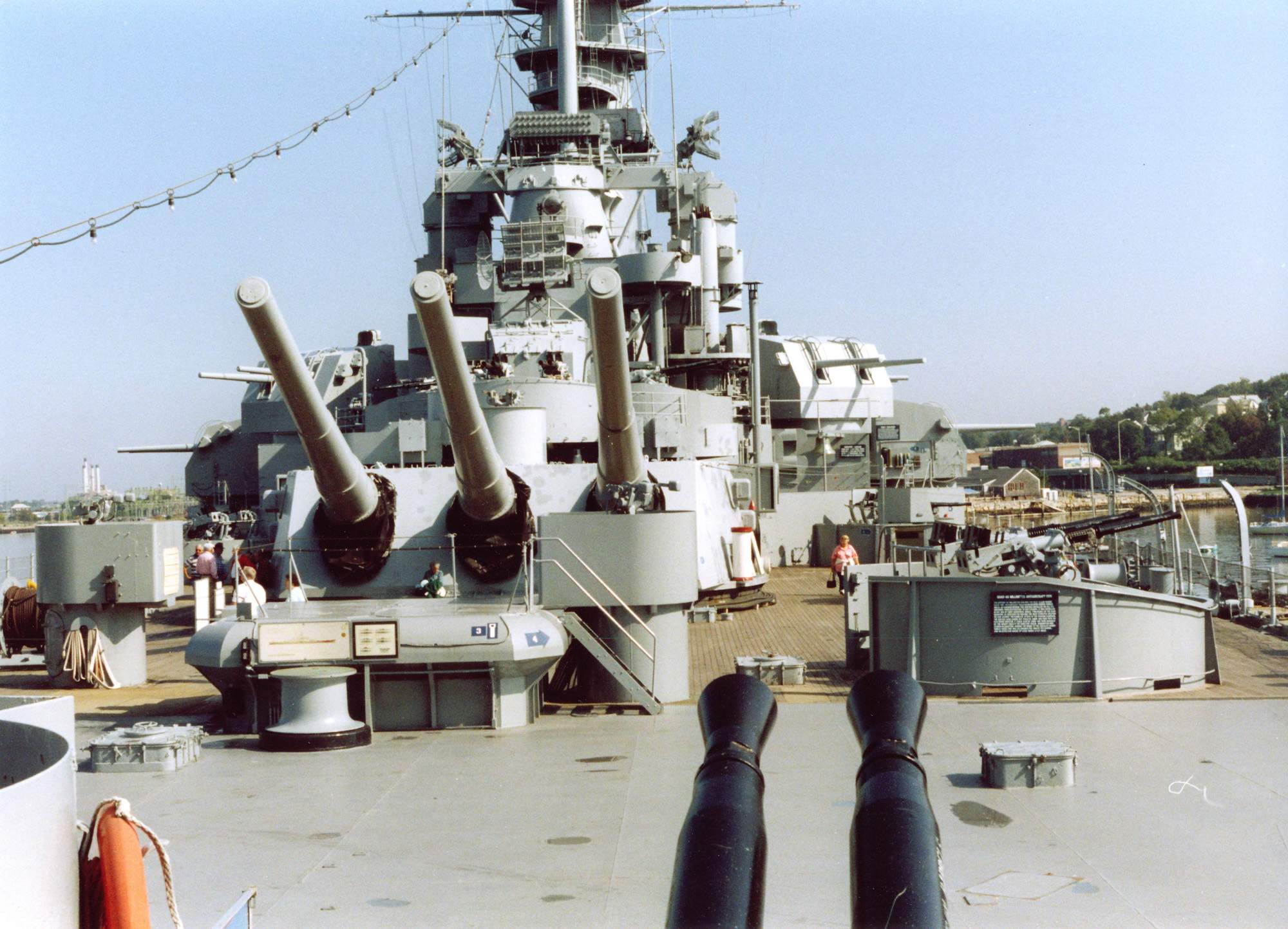
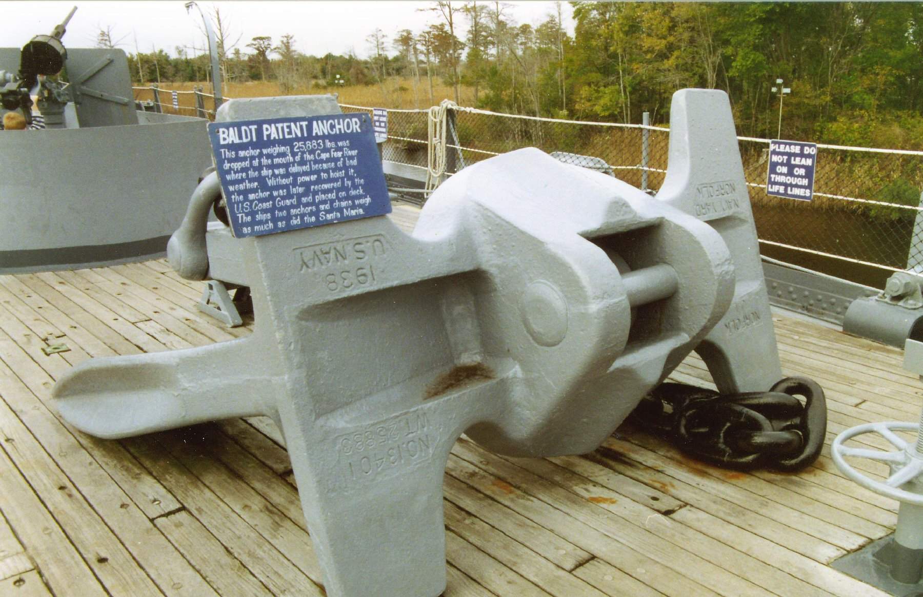
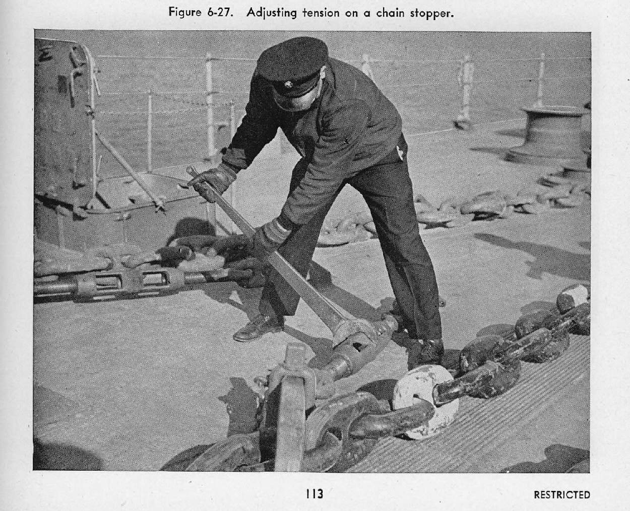
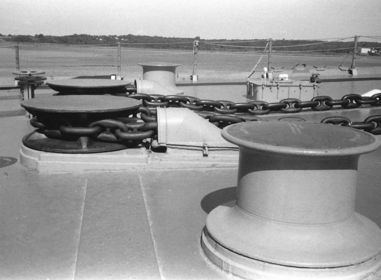
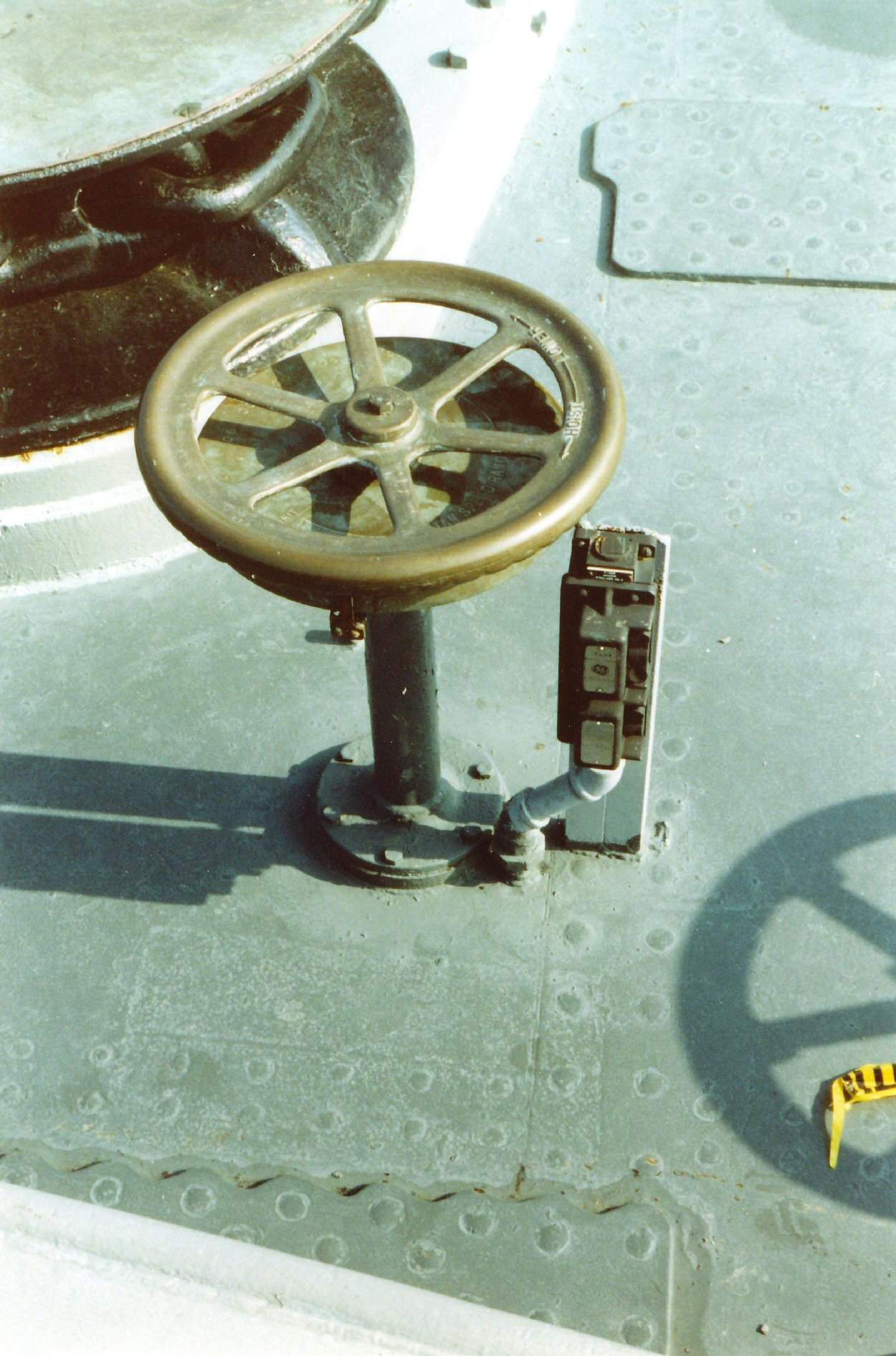
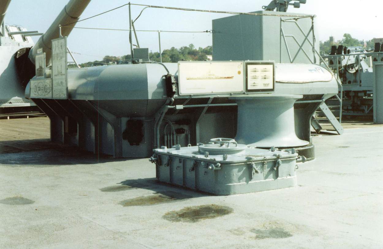
 | 150k | The anchor handling machinery consisted of two similar vertical windlass (winch) units, one to port and one to starboard, each complete in itself but capable of being cross-connected hydraulically for emergency operation if required. Each unit had been designed to hoist a 25,000 pound anchor [anchor pictured is from the North Carolina (BB-55)] and 60 fathoms of 3-inch heavy duty, die-lock steel chain at a full speed rate of 6 fathoms per minute, a suitable allowance having been made for hawse pipe friction. This is equivalent to a chain pull at the wildcat (a shaped drum on a windlass, engaging with the links of an anchor chain) of 83,000 pounds and an operating pressure of 695 pounds per inch in the hydraulic system. If it became necessary to handle loads greater than this, the hydraulic pump could be operated at a reduced stroke. This reduced the chain speed and prevented overloading the electrical equipment. The maximum capacity was then limited by the relief valves, which were set at 1390 pounds per square inch. The capstan head seen here (with wildcats) on each unit was designed for a rope pull of 15,000 pounds at a maximum speed of 125 feet per minute using 10-inch circumference manila rope. Each power unit consisted of a continuously operating 225 HP General Electric Company motor, equipped with a thrusters type electric brake of 325 ft./lb. rated capacity, connected by flexible couplings with a reduction gear unit and a size 50K Waterbury hydraulic pump (or A-end). The A-end shaft turning constantly in one direction, was connected to the B-end by piping. The amount and direction of oil flow through this piping was determined by the control spindle on the A-end, as for all Waterbury Speed gears in general. The B-end was mounted vertically on the case which enclosed the main train of driving gears for the vertical wildcat and capstan shafts and drove the shafts through this train. The capstan shaft was coupled to the driving gear unit without a disconnecting clutch but the wildcat shaft was driven through a locking head which was keyed to the shaft near its bottom. This locking head was fitted with two sliding vertical block keys which could be engaged with suitable pockets in the main driving gear for transmitting power to the wildcat or withdrawn if desired to leave the wildcat free. The block keys were actuated by levers on the locking head. Before the wildcat was disconnected, the mechanical brake which was mounted on the shaft just above the half deck had to be applied to secure the wildcat, particularly when the capstan was used. The brake could also be used to control the run of chain when the anchor was dropped free. A speed control handwheel and a brake handwheel were mounted on the Main Deck for each windlass unit with duplicated wheels in the windlass room for emergency use. The speed control wheels were fitted with indicating scales to show speed and direction of rotation. Four way transfer valves were installed in the piping between the A-ends and the B-ends of the hydraulic units. As normally set these valves connected the port A-end to the port B-end and the starboard A-end to the starboard B-end. If an emergency required it, the valves could be turned to cross-connect the units by connecting the port A-end to the starboard B-end and the starboard A-end to the port B-end. Relief valves were provided on the above piping at each main pump to limit the hydraulic pressure to 1390 pounds per square inch in order to protect the machine against excessive loads. Replenishing valves built into the A-end valve plate, automatically passed oil from the case into the suction port to make up the small leakage loss in the active oil. They would not permit flow in the opposite direction. An air vented oil expansion tank, provided at the highest point in the hydraulic system was connected to the cases of the hydraulic pumps and motors. It served as a reservoir in connection with the functioning of the valves and took care of the expansion of heated oil and helped to dissipate the heat. A pressure gauge, mounted convenient to the power unit, was provided for each hydraulic unit. The gauge was piped to the A-end nozzle which was under pressure when hoisting the anchor. A centering device was incorporated in the control shafting to facilitate locating the A-end in neutral (or no-stroke) position. An interlock switch was also provided which prevented starting the main motor if the control was not in neutral and thus prevented starting the motor under load. In the event of current failure during operation, the electric brake would apply automatically and support the load being handled. Lubrication of the main gear reduction units was by means of a forced feed system. When breaking out the anchor or otherwise requiring the maximum chain pull that could be obtained, as determined by the setting of the relief valves, the control wheel had to be set for reduced pump stroke. This would lower the driving torque required by the pump and prevented stalling the electric motor or tripping the overload protection. The rate of speed at which the cable was hove in was proportionally reduced but the greatest possible pull was made available. Note: The submarine in the background is the Lionfish (SS-298). | USN photographs courtesy of Pieter Bakels & Alan Raven. Text Source: General Information Book, Massachusetts (BB-59), 1942. | |
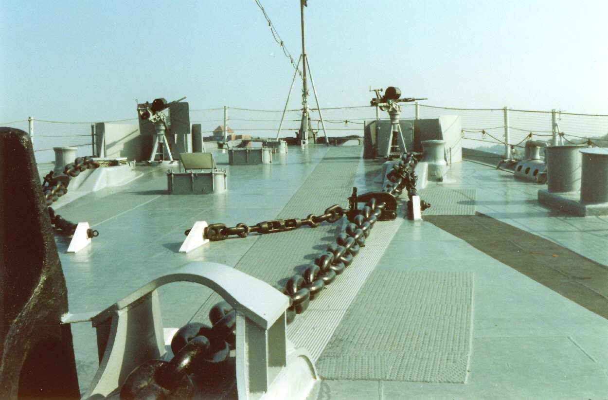
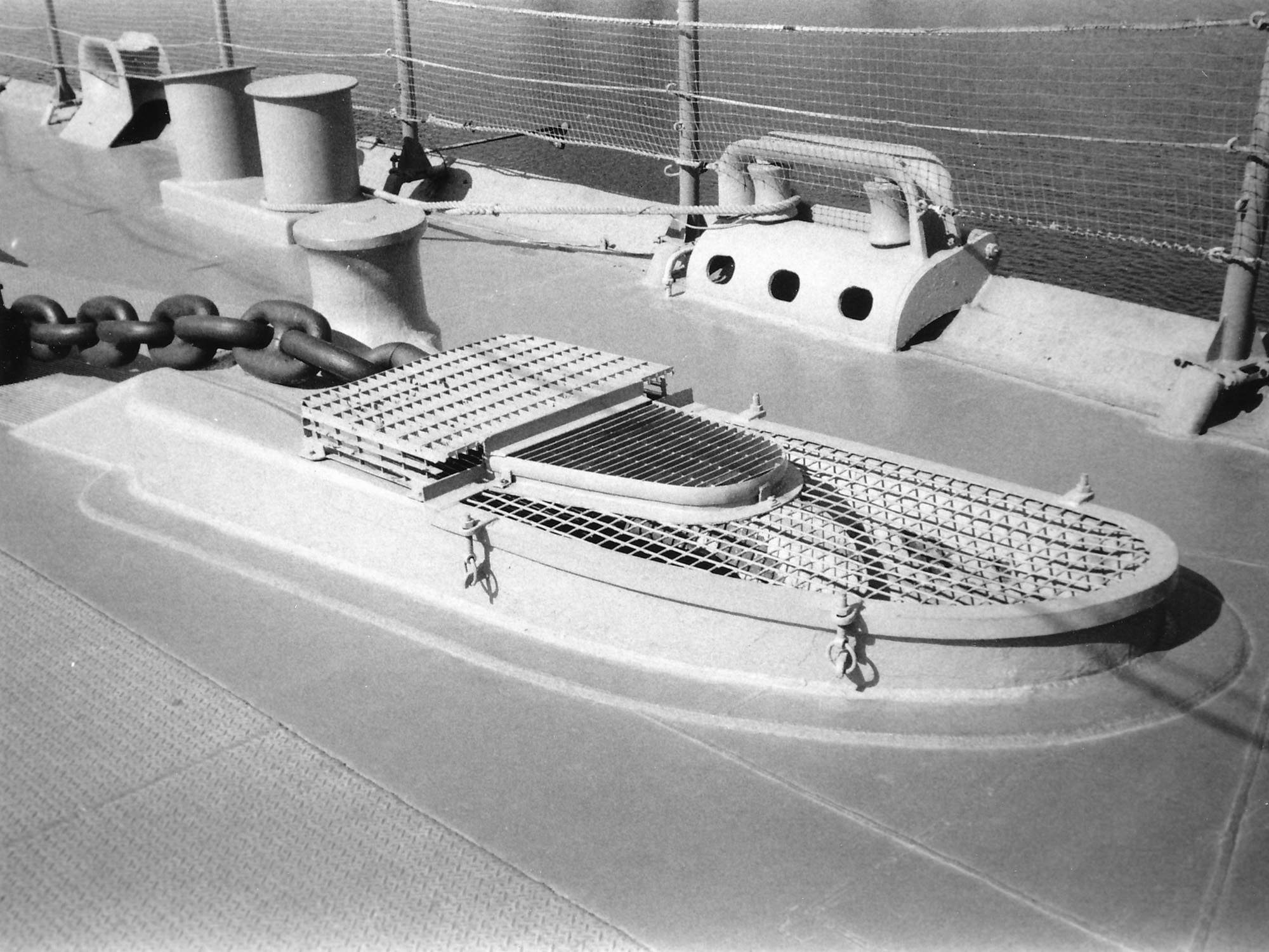
 | 290k | Capstan: One electric worm gear capstan head manufactured by C.H.Wheeler Manufacturing Company with a capacity of 15,000 pounds at 50 feet per minute or a light line speed of 130 feet per minute, was installed on the main deck aft between frames 144 and 146 to port of the centerline of the ship for handling the stern mooring lines. | Photo courtesy of Pieter Bakels. | |
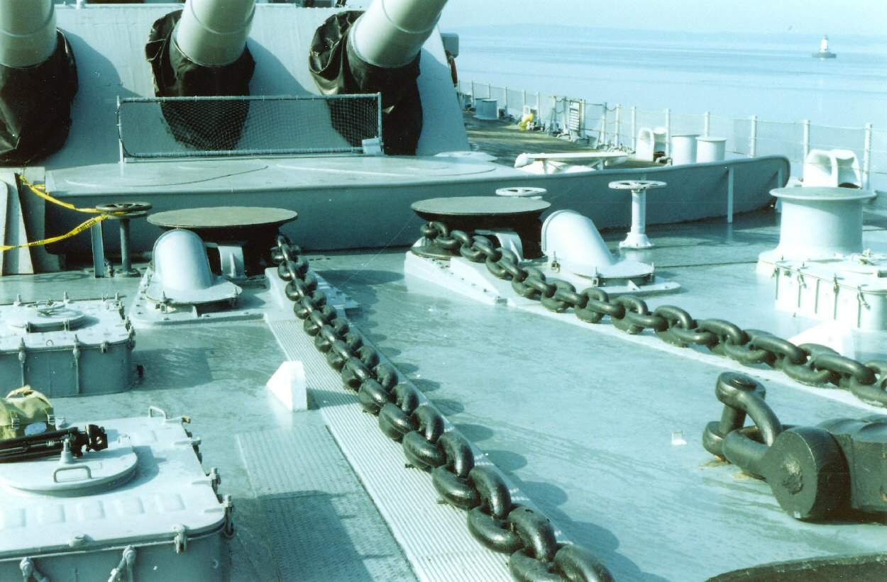
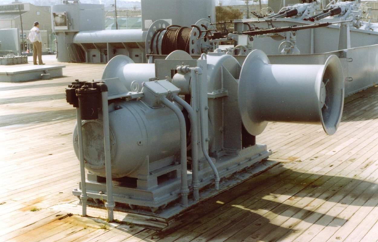
 | 114k | Deck Winch:
Two double gypsy electric worm gear reduction winches, manufactured by M.L. Bayard & Company, Inc., were installed on the Main deck aft between frames 126 and 129 for use in handling aircraft recovery lines and mooring lines with a capacity of each Gypsy of 15,000 pounds at 62 feet per minute or 7,500 pounds at 125 per minute. One Deck Winch is installed on the port side and one on the starboard side. | Photo courtesy of Pieter Bakels. | |
| Back To US Battleship Construction Index | Back To The Main Photo Index | Back To The Battleship Photo Index Page |
This page is created by Pieter Bakels and Michael Mohl & maintained by Michael Mohl
All Pages © 1996 - 2025, by Paul R. Yarnall NavSource Naval History. All Rights Reserved.