| Click On Image For Full Size Image |
Size | Image Description | Contributed By And/Or Copyright |
|
|---|---|---|---|---|
 |
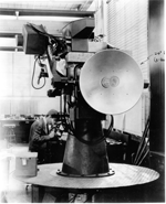
2.2m | The image on left is a pre-production model of G.F.C.S. Mark 60 Mod.0. Gun Fire Control System MK 60 was developed as a more satisfactory director for optical or blind-firing control of 40mm guns than both Mk 57 and Mk 63 and consisted of three major components, namely, Gun Director Mk 60 Mod 0, Gun Sight Mk 26 Mod 0 and Radar Equipment Mark 36 Mod 0, a K-band radar for limited antenna size (24”). 1,000 Mk 60’s were ordered but production problems ended the program. All the components were designed by the General Electric Company with emphasis on simplicity, compactness, ease of operation and maintenance. Furthermore, the whole system was relatively light (2600 lb.) with topside equipment weighing about 1.250 lbs. Gun director Mk 60 Mod 0 was similar to Mk 52 in appearance and required a 6’ working circle. Gun sight Mk 26 Mod 0, the antenna reflector and the blind-tracking indicator unit of radar equipment Mk 36 Mod were mounted on the director. Gun sight Mk 26 Mod 0 was a small lead-computing sight, which operated on the disturbed line-of-sight principle with the sight being very similar to that of gun sight Mk 20, having a single electrically driven gyro which had two degrees of freedom. This gyro had been fitted with magnetic pick-offs which measured the lead-angles developed in tracking. Radar equipment Mk 36 Mod 0 was an x-band, conical scan fire control radar. In addition to pointing, i.e., indicating the target position in train and elevation to the operator, the radar automatically furnished range information to gun sight MK 26 for both optical and blind-firing. Radar pointing with radar range and optical pointing with estimated range, therefore were all possible. A special search feature was incorporated in which the radar reflector could be moved in a vertical plane through an angle of 20 degrees at a frequency of 1.5 cycles per second. This feature aided the operator in target acquisition. The fundamental principles of operation were similar to those employed by Gun Director System Mk 58 - it operated on the disturbed line-of-sight principle, familiar in the Fleet, since it had been incorporated in Gun sight Mk 14. Lead angle and ballistic computations were made by gun sight Mk 26 which was mounted on the director tracking head. It’s operator moved the director in train and elevation. |
Photos & text courtesy of Pieter Bakels. | |
| Back To US Battleship Construction Index | Back To The Main Photo Index | Back To The Battleship Photo Index Page |
This page is created by Pieter Bakels and Michael Mohl & maintained by Michael Mohl
All Pages © 1996 - 2025, by Paul R. Yarnall NavSource Naval History. All Rights Reserved.