| Click On Image For Full Size Image |
Size | Image Description | Contributed By And/Or Copyright |
|
|---|---|---|---|---|
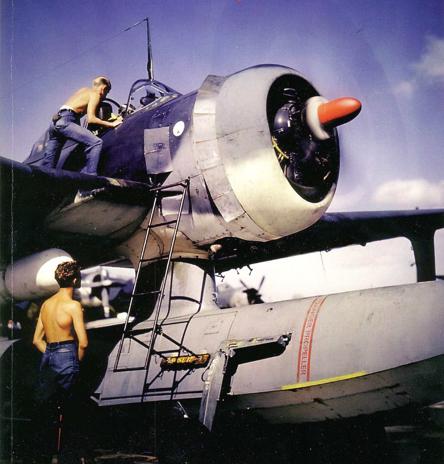 |
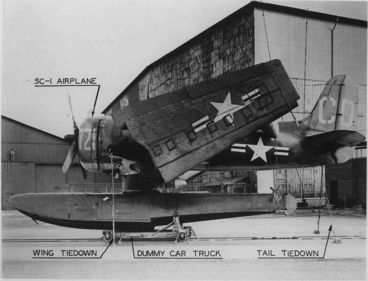
341k | The SC-1 "Seahawk" was the last of the scout observation types and designed to replace obsolete predecessors in the reconnaissance role.
It also was the most highly developed. It was a highly versatile aircraft with vastly improved performance over earlier types like the venerable Kingfisher. Power, range and armament had doubled its usefulness. The lone scout was no longer a sitting duck for enemy aircraft. Highly maneuverable, with two forward firing .50 cal. guns, it could protect itself well. Large flaps and automatic leading edge slats improved slow speed characteristics. Radar as external store was carried on the underside of the starboard wing, which proved highly successful during search missions. Space saving aboard ship was accomplished by folding the wings back manually, making the overall width equal to the span of the horizontal tail surfaces. A novel was the internal bomb bay in the central float, later utilized for an additional fuel tank, with watertight bomb bay doors, actuated from the cockpit. It was liked by some pilots and disliked by others, but generally well accepted. The SC-1 could out-climb an F6F "Hellcat" to 6,000 ft. and out-turn the F8F "Bearcat". Its great power made it almost mandatory to make a water take-off 30 degrees out of the wind- engine torgue pulled the aircraft automatically into the wind. Some trouble was encountered with the leading edge slats. These automatic slats were designed to come out when airspeed dropped below 90 knots. They sometimes would pop out while doing 150 knots or when the plane was in a steep turn. These cases were not wide spread and corrective mechanical measures kept them to a minimum. Losses with the "Seahawk" were high, mostly caused by the extremely hazardous conditions in which they operated. Too hard a water landing and the engine would drop, the propeller cutting through the float. Several mishaps occurred due to a faulty auto-pilot system. Aircraft and pilots were lost due to unknown landing accidents. It wasn't until one pilot "walked-away", that it was discovered that the auto-pilot was taking over on landings. As a result, all automatic pilot systems were made inoperative on all SC's. During the height of their career, crews aboard ship looked with pleasure at the "Seahawks" aft on the catapults as their "Quarterdeck Messerschmitts". The SC-1 first flew in February 1944 and 950 were ordered, later decreased to 566 because of the Victory in the Pacific. It continued in service for a number of years after the war as trainers. Only 9 SC-2's were completed. It had an up-rated engine with an improved cowl design, a larger fin and rudder and a "blown" canopy. Paint scheme: Post January 1943 Upper surfaces: Non-specular Sea Blue (#35042). Mid surfaces: Non-specular Intermediate Blue (#35164). Lower surfaces: Non-specular Insignia White (#37875). SC-2 Post January 1943 - the same as above. 1947 scheme: overall glossy Seablue (# 15042)with white numbers and letters & red bar in U.S. insignia in four positions. |
Drawing courtesy of George Lee & submitted by Pieter Bakels. Text courtesy of Pieter Bakels via "Catapults" Type P, MK.VI, with Catapult Gun MK.VI,etc., Bureau of Aeronautics, October 1, 1942. And Report # N-4759, Rev.-1, 21 May 1948- "Securing and Stowage of Seaplanes aboard Battleships and Cruisers", Naval Air Material Center, US Naval Base Station Philadelphia, PA. | |
 |
341k |
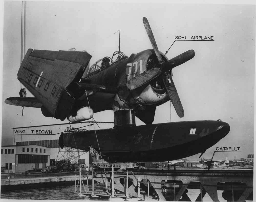
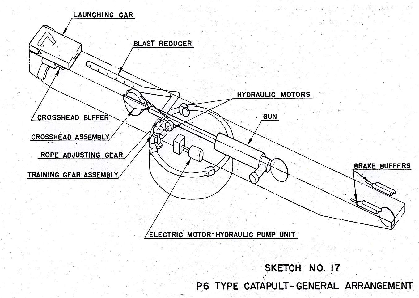
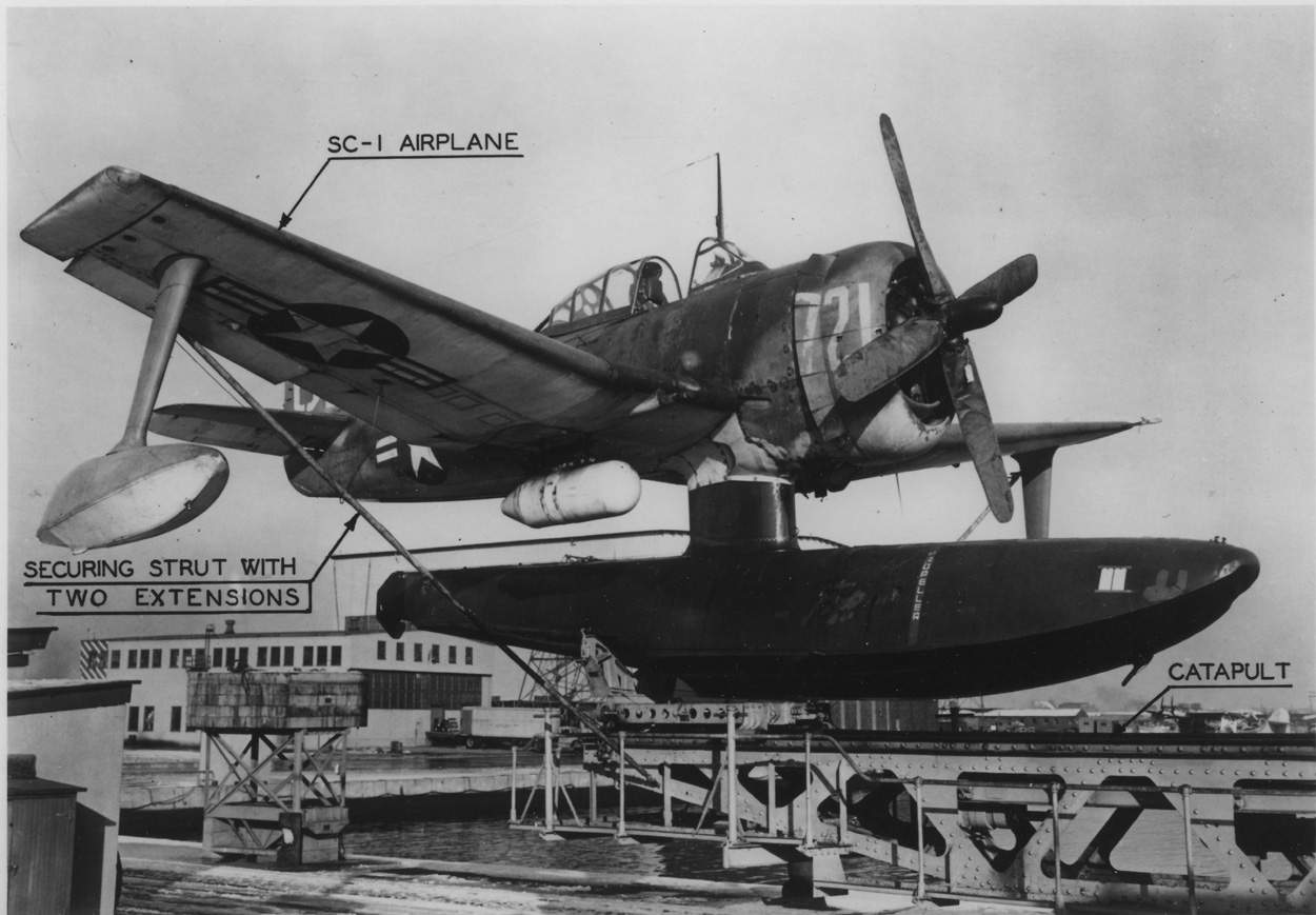
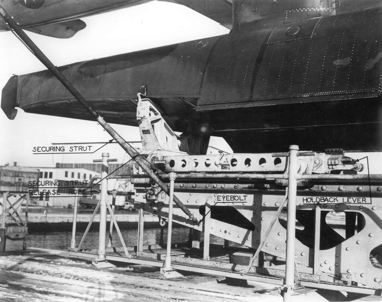
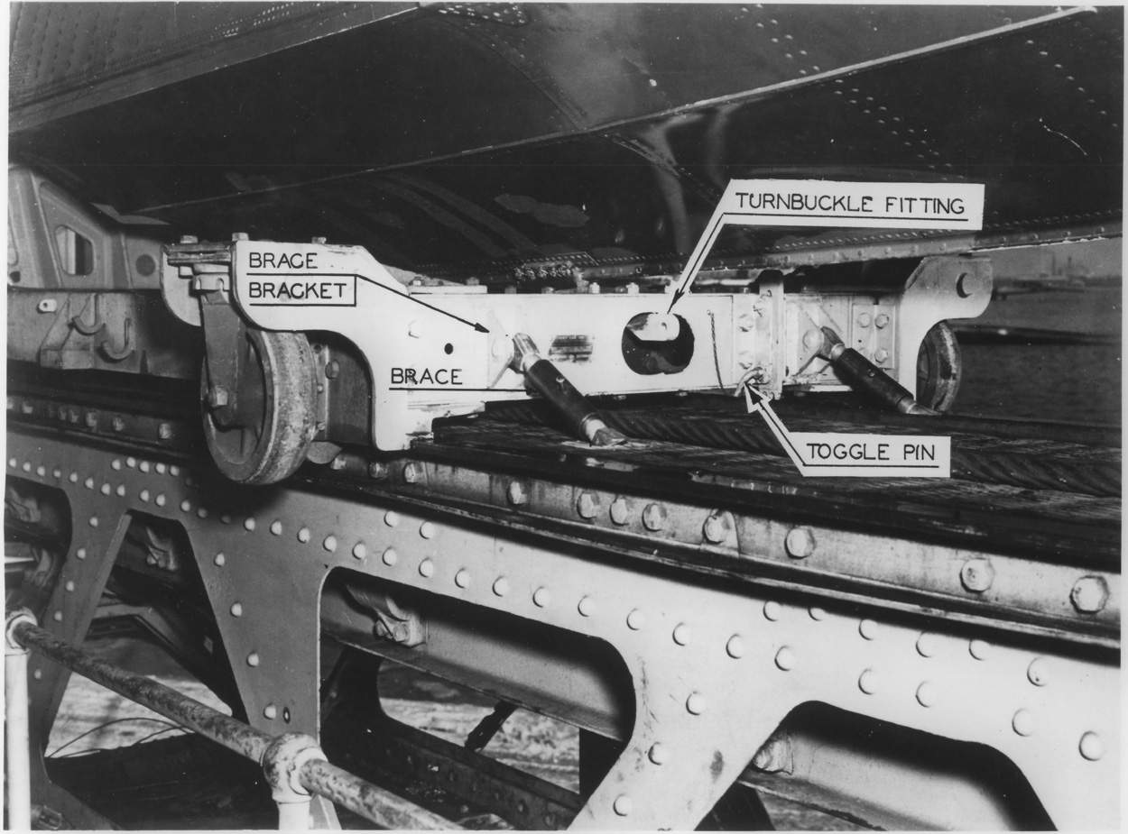
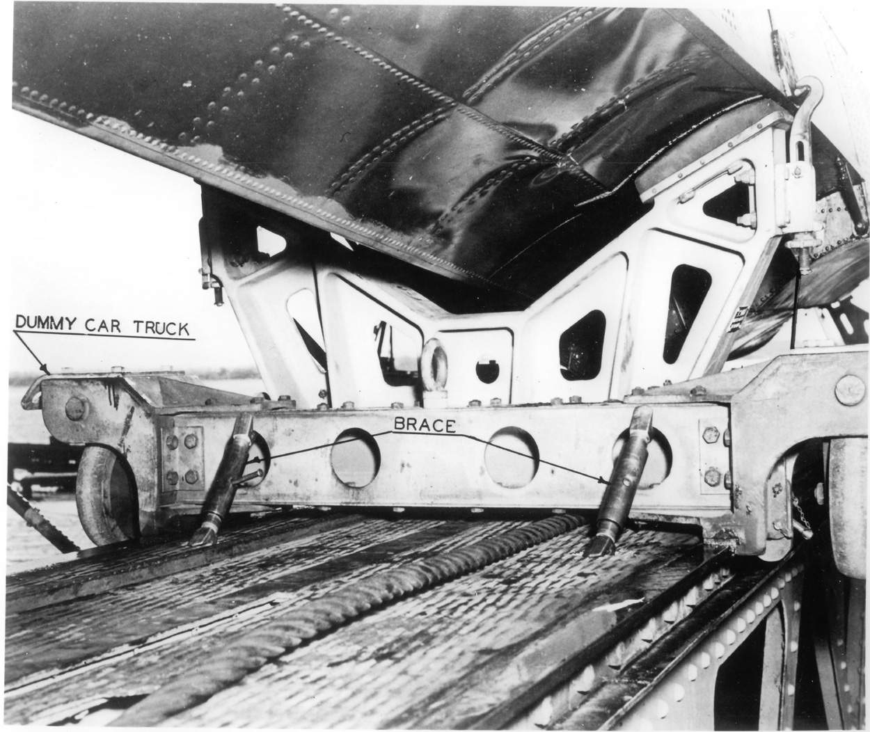
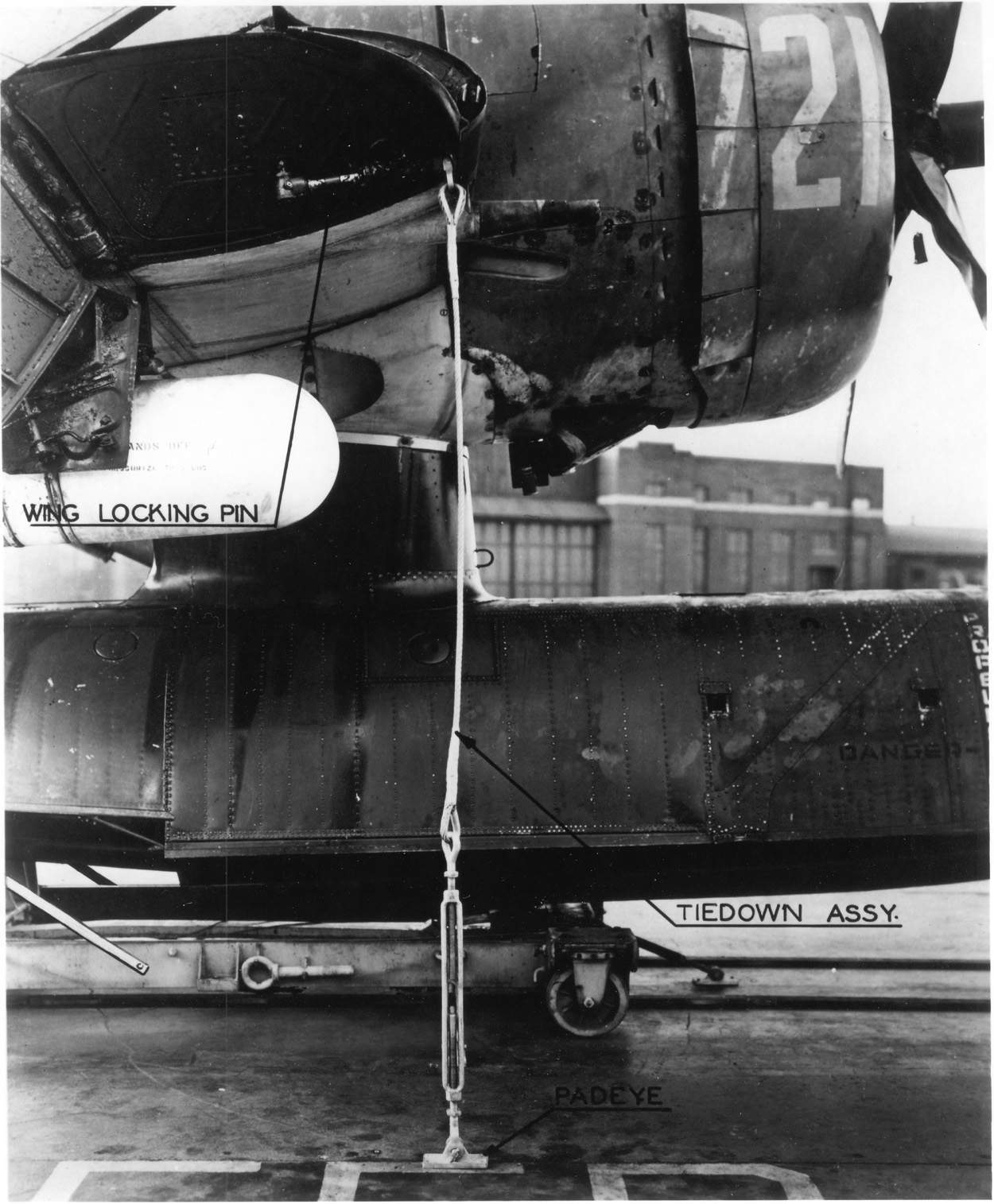
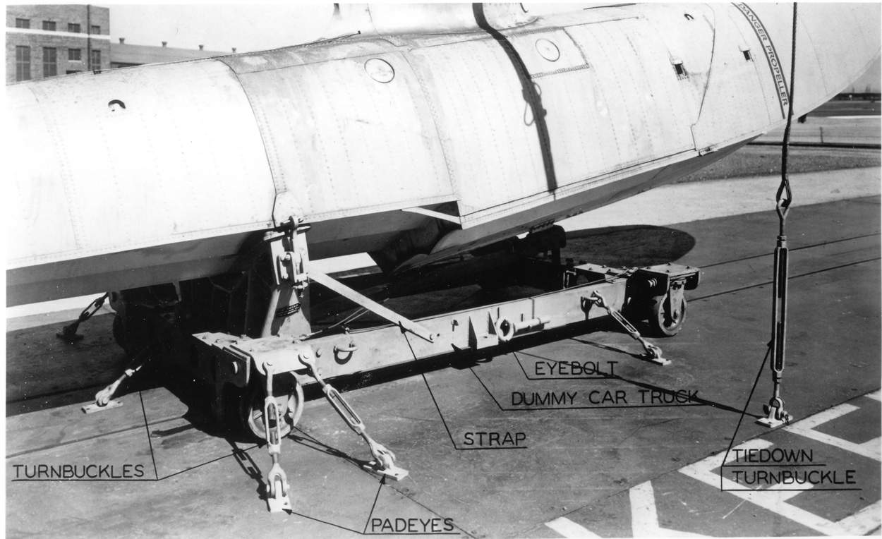
The capacity to gun and catapult was limited to a combined launching and aircraft weight of 8150 pounds at an end speed of 65 miles per hour.
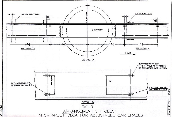
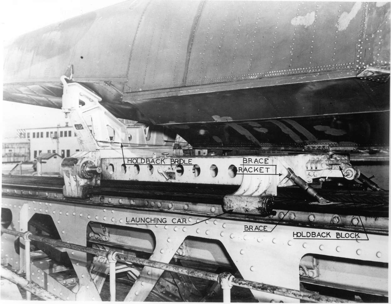
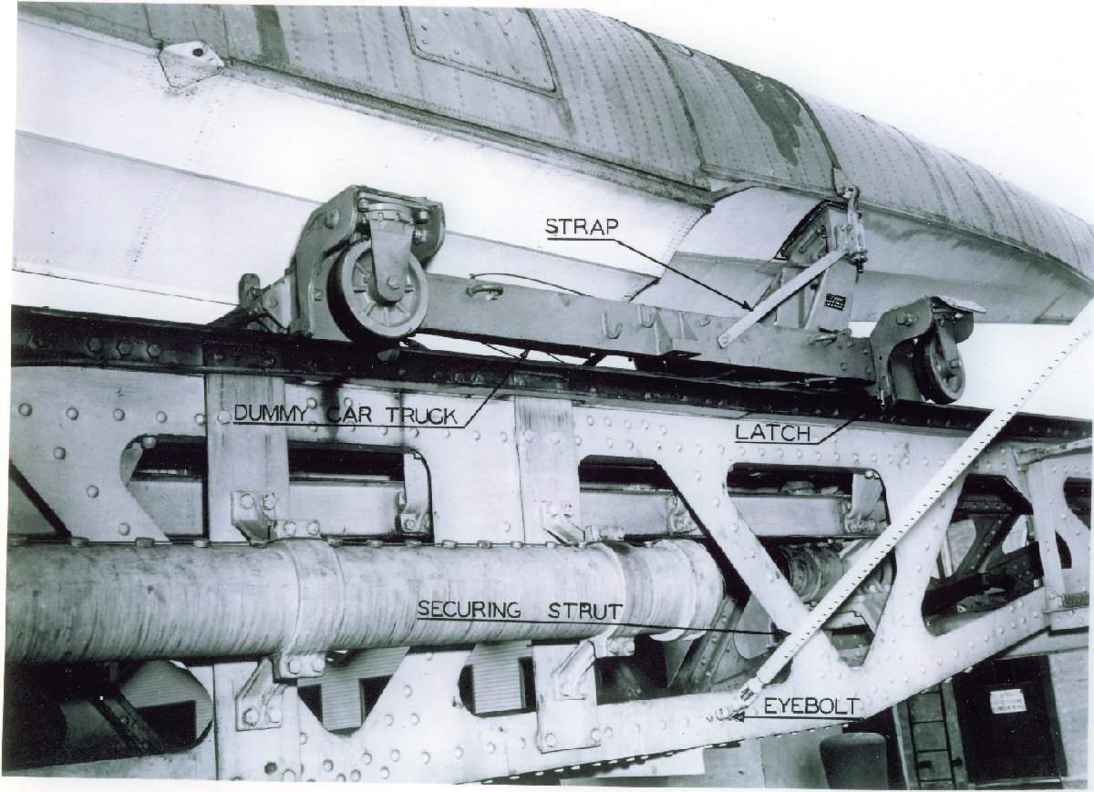
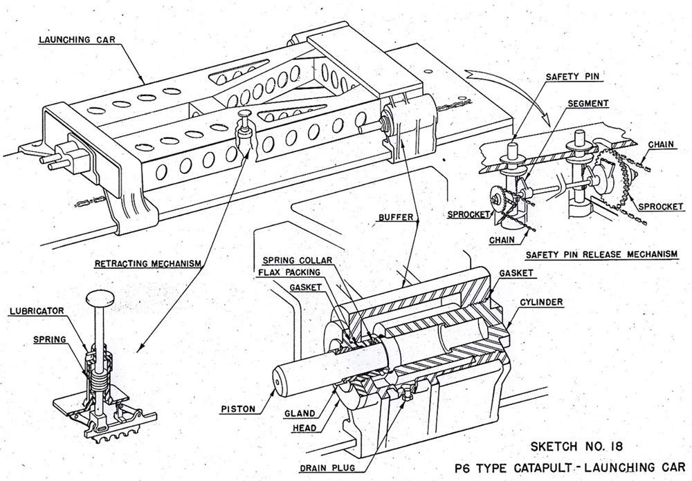
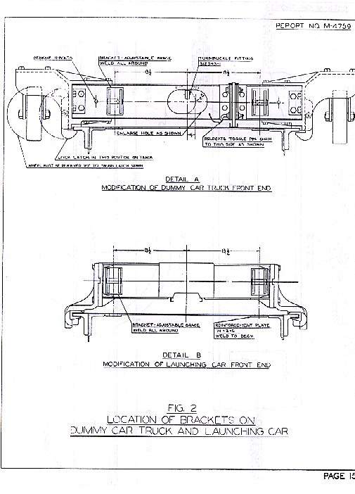
The "Seahawk" above appears with it's Wright R-1820/62 nine-cylinder, single row, air-cooled engine warming up, running full out, ready for take off, in battery position. Stowed in battery, wings folded. The aircraft is secured to the launching car with safety pins engaged and holdback lever in position, the wing tie downs are rigged between wing locking pins on the aircraft and the crossmember on the catapult. The turnbuckles have been tightened until the tiedowns were taut. Stowage in battery wings unfolded. Stowage in battery - tiedown arrangement. Note the AN/APS-4 radar in the off-white fibreglass housing. Wing tiedowns were used to secure the aircraft when it was stowed with its wings folded. They consisted of a ˝ inch diameter wire rope, which had a link attached to one end designed to fit the wing locking pin fitting of the aircraft and a turnbuckle spliced to the other end that fastened to lugs on deck (or the crossmember, - on CL's and CA's only). Stowage in battery, securing strut location. The eyebolts were located at the lower chord of the catapult structure at each of the three stowage positions of the aircraft. They had to be located in such manner that the securing struts when attached were straight and perpendicular to the centreline of the catapult. Securing struts should never be attached to the launching car or dummy truck eyebolts. Fastened in this position they were virtually ineffective. They had to be attached to eyebolts placed low on the catapult structure for maximum advantage. The launching car was used on catapult type ”P” to stow as well as launch seaplanes. It required the use of a saddle to fit the aircraft. The SC-1 was secured via stowage on a aft-dummy car truck secured to catapult track. Adjustable braces were used to lock the launching car and dummy car in position on the catapult. Seaplane stowage aboard ship was as follows: 1.On launching car-in battery-wings folded. 2.On launching car-forward of turntable-wings unfolded, used when a second aircraft is stowed on the dummy truck aft of the turntable. 3.On dummy car truck-forward of battery-wings unfolded. 4.On launching car-in battery-wings folded, used only on cruisers when a second aircraft was stowed on the hatch cover. 5.Deck, hatch cover, elevator or hangar stowage on dummy car truck-wings folded. 6.Deck stowage on dummy car truck-wings unfolded-used sometimes on battleships. The attitude of the dummy car truck could be adjusted aboard ship to headroom in a hangar. Trucks on battleships had to be set in the maximum nose-down position. Most cruisers required a higher setting, determined by hangar clearance and trial. Do not set the nose any higher than is necessary to get clearance over the wing tips in the hangar. The aircraft was accelerated to flying speed on the launching car, guided along the catapult by means of highly polished tracks. Wing tie downs were used to secure the aircraft, when stowed with folded wings. Each truck had eight turnbuckles for securing it to the deck and two locating pins for spotting it on an elevator or in close quarters. All eight turnbuckles always had to be used! The casters had to be locked to prevent the wheels from swivelling. When stowed on deck, the loaded truck had to be secured and the aircraft tail rigged exactly the same as when secured with the wings folded, except that the wing tiedowns could not be used and special provisions had to be made in order to use securing struts in their stead. Unless the securing struts had their lower ends fastened to the deck, they would not brace the aircraft and truck against overturning forces. The ship's structure required the following changes: Two lugs had to be provided on the deck to which the securing struts could be connected. The lugs had to be located in such manner that the securing struts were placed at the steepest angle the clearance of the strut fitting would permit. Lug strengths had to be equal to that of the securing strut, or approximately 6500 pounds. 10 new flush deck fittings at each aircraft stowage position likely to be used on deck and 2 ring bolts or other suitable flush type deck fittings had to be provided, suitable for tying down the aircraft tail with 3/8 or ˝ inch diameter manila rope. SC-1 Aircraft wing tie down assy. Before launching, the car was secured in battery position by a tension ring and two safety pins, made of steel and designed to break. |
Drawing courtesy of George Lee & submitted by Pieter Bakels. Text courtesy of Pieter Bakels via "Catapults" Type P, MK.VI, with Catapult Gun MK.VI,etc., Bureau of Aeronautics, October 1, 1942. And Report # N-4759, Rev.-1, 21 May 1948- "Securing and Stowage of Seaplanes aboard Battleships and Cruisers", Naval Air Material Center, US Naval Base Station Philadelphia, PA. | |
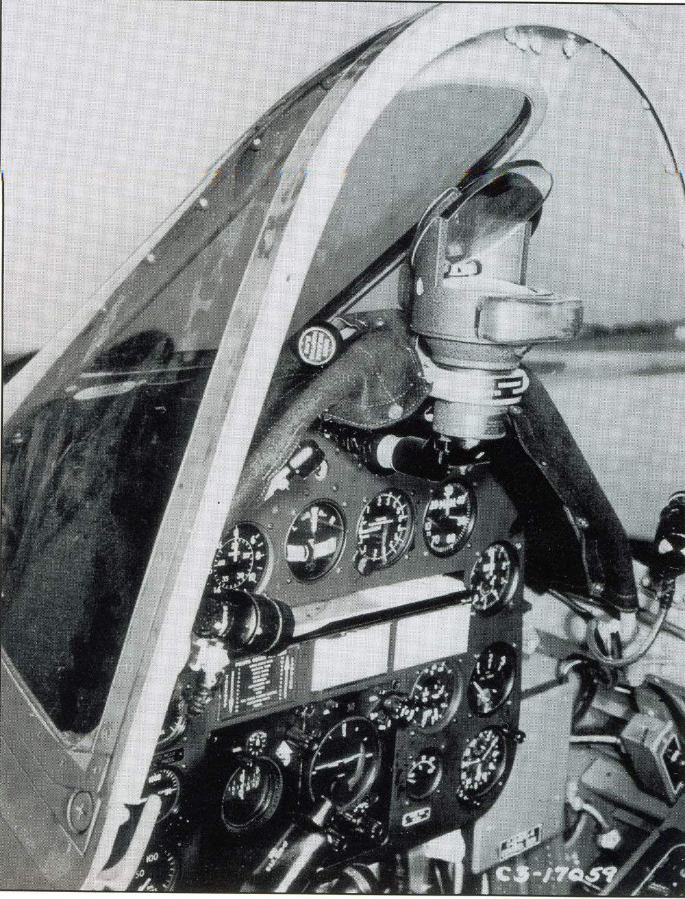 |
306k | SC-1 forward cockpit and windsscreen frame. Note the map board and slot below the 1st row of instruments. | USN photo submitted by Pieter Bakels. | |
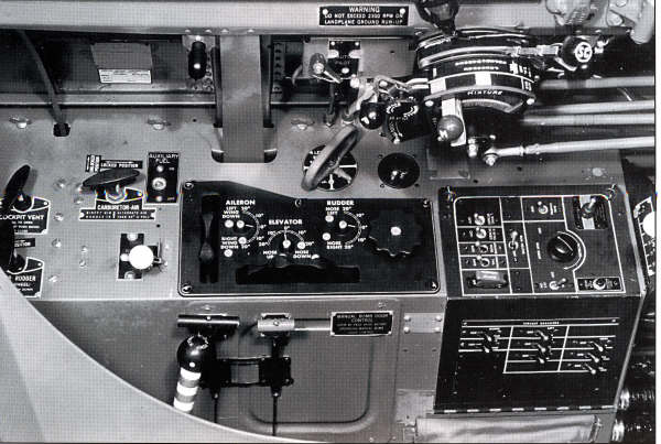 |
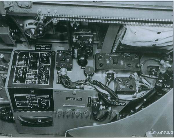
50k | SC-1 Pilot's left side console, trim tab controls, armament panel and circuit breakers. | USN photo submitted by Pieter Bakels. | |
 |
48k | SC-1 Pilot's right side console. | USN photo submitted by Pieter Bakels. | |
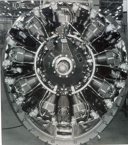 |
63k | The engine of the SC-1 was a Wright R-1820-62 or -62A nine cylinder,radial,air-cooled model with integral single speed supercharger. | USN photo submitted by Pieter Bakels. | |
| Back To US Battleship Construction Index | Back To The Main Photo Index | Back To The Battleship Photo Index Page |
This page is created by Pieter Bakels and Michael Mohl & maintained by Michael Mohl
All Pages © 1996 - 2025, by Paul R. Yarnall NavSource Naval History. All Rights Reserved.